Continue to Site

Welcome to our site!

Electro Tech is an online community (with over 170,000 members) who enjoy talking about and building electronic circuits, projects and gadgets. To participate you need to register. Registration is free. Click here to register now.

  • Welcome to our site! Electro Tech is an online community (with over 170,000 members) who enjoy talking about and building electronic circuits, projects and gadgets. To participate you need to register. Registration is free. Click here to register now.

PIC 12F675 Comparator, Few Questions .

Status
Not open for further replies.

aljamri

Member
Hi,

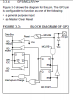
I'm doing 12F675 from this link:

Using the built in 12F675 Comparator.

Following, is the code:

Code:
// Definitions
#define COMPARATOR_OP 2
#define LED 4

///////////////////////////////////////////////////////
void init_ports(void) {
   //GP0 & GP1 are inputs
   TRISIO = 0 | (1<<GP0) | (1<<GP1); // 0 - op, 1 - ip

   ANSEL = (1<<GP0) | (1<<GP1); ; // Ana. ip on GP0 GP1
}

///////////////////////////////////////////////////////
void init_comparator(void) {
   // Comparator with external input and output.
   // Cout = 0 (comparator output), Cinv =0 (inversion)

   [COLOR="#ff0000"][B]CMCON = 0x01;[/B][/COLOR]

}

///////////////////////////////////////////////////////
// Start here
void main() {
int i;

   init_ports();

   // Show device is active on power up.
   for (i=0;i<5;i++) {

      GPIO |= (1<<COMPARATOR_OP);
      delay_ms(100);

      GPIO &= ~(1<<COMPARATOR_OP);
      delay_ms(100);
   }

   init_comparator();

   while(1) {;
      GPIO |= (1<<LED);
      delay_ms(100);

      GPIO &= ~(1<<LED);
      delay_ms(100);
   }
}

The code works fine using the provided circuit. Then I've replaced the comparator Potentiometer VR1 with a 10k resistor in series with LDR. The circuit still works fine, The output LED D1 stays OFF, and when LDR covered, It turns ON.

I have few questions regarding the comparator and the code and here is the first:

Trying to measure my understanding, I've tried to reverse the D1 ON/OFF status by , changing CMCON command from 0x01 to ox81 ( changed Bit6 COUT from 0 to 1 ).

When programmed the PIC, the operation does not changed. What do you think is wrong?
 
Ohhhh, You are right, I've put 9 digits instead of 8. Tomorrow I'll check it and let you know. Then I'll go to the next Question.
Thanks
 
Bit4 CINV is the output Inversion bit

1 = Output inverted, so CMCON = 0x11 will make my LED ON in dark and OFF in light ( using LDR )

this operation is confirmed.
 
My 2nd Question is :

How to utilize the comparator action in my program. Instead of a stable 1 at output, I need to output a square wave to drive a buzzer using any other unused pin. So that I've added the following 2 lines:

Code:
switch (GPIO.F2) {
      case (0) : GPIO.F3=0;
      case (1) : GPIO.F3=1; delay_ms(500); GPIO.F3=0; delay_ms(500);
                  }

but got no output on GP3 regardless the comparator condition. Is there another idea ?
 
O.K. second chance at it, GP3 (MCLR) is input only pin, try GP5. Or use GP2 by setting up the CMCON register for no output.
 
GPO3 is input only

CLRF GPIO ;Init GPIO
MOVLW 07h ;Set GP<2:0> to
MOVWF CMCON ;digital IO
BSF STATUS,RP0 ;Bank 1
CLRF ANSEL ;Digital I/O
 

Attachments

  • mclr_GPIO3.PNG
    mclr_GPIO3.PNG
    18.7 KB · Views: 265
Yes, I've used GP5 as output and got everything working fine. My buzzer is sounding whenever it is dark. My next step is to immigrate the same program into a larger PIC such as 16F6XX and 16F7XX and try to test all their comparators and let you know my progress.

Thanks for all.
 
It's a will be easy to reuse your code with 16f6xx chips just a little name changes and you'll be good to go
 
Tried to get it work on PIC16F628A but no chance. Here is the code:

Code:
void init_ports(void) {

   TRISA = 0x0F; // RA.0:RA.3 INPUTS
                 // RA.4:RA.7 OUTPUTS
}

void init_comparator(void) {
   // Both Comparators with external input and output.

   CMCON = 0x04;
}

// Start here
void main() {
int i;
//
   init_ports();
//
//   // Show device is active on power up.
   for (i=0;i<5;i++) {

      PORTA.F2 = 1;
      delay_ms(100);

      PORTA.F2 = 0;
      delay_ms(100);
   }


   init_comparator();

   while(1) {;
   
      PORTA.F6=1;delay_ms(500);PORTA.F6=0; delay_ms(500);

                           }
}

The last part of the code is working fine, the LED conncted to PortA.F6 is flashing, but Comparator 2 output at RA4 shows no difference regard less the change in its inputs, RA1 (adjustable) and RA2 2.5V via 10K resistor as a reference.
 
Status
Not open for further replies.

Latest threads

Back
Top