Continue to Site

Welcome to our site!

Electro Tech is an online community (with over 170,000 members) who enjoy talking about and building electronic circuits, projects and gadgets. To participate you need to register. Registration is free. Click here to register now.

  • Welcome to our site! Electro Tech is an online community (with over 170,000 members) who enjoy talking about and building electronic circuits, projects and gadgets. To participate you need to register. Registration is free. Click here to register now.

Phototransistor Circuit

Status
Not open for further replies.

John 2010

New Member
Pulling my hair out at the moment. I'm not the World's expert on electronics but have been trying to simply copy a design for the following:

How to Make a Laser Alarm | eHow.co.uk


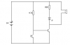
I've followed the 'plan' using a Farnel 970-7808 phototransistor.

The only difference between my unit and the plan is that I've replaced the 12V siren with a mega bight blue LED and 169ohm resistor (intension was to have bank of LEDs once functioning).

Is my trading the LED for the siren the problem or is the diagram faulty?

I've triple checked my work - fairly neat on an IC board and it all seems fine.

Your assistance would be very much appreciated

Thanks

John (UK)
 
That's got to be the most complicated way of drawing such a simple circuit.

The circuit isn't very good, besides the schematic lists a photoresistor and you're using a phototransistor, not that it should make any difference.

Try this circuit and make sure that the phototransistor is well shielded from ambient light.

EDIT:

169Ω is far too lower value resistor to power a typical LED off 12V, I suggest increasing it to 680R.
 

Attachments

  • Simple dark dete&#99.PNG
    Simple dark dete&#99.PNG
    616 bytes · Views: 445
Last edited:
Thank you hero999,

I agree! and I'm no electronics guy - infact I redrew it in order to make sense of it

Why is the circuit not very good? I just wondered what your opinion was and how I could improve it?

It will be working outside so ambient light will have to be minimised through a black tube (not being used to stop burglars!)

My LEDs are as follows:
Max Voltage Vf:4V
Forward Current:30mA

Using 9V - is my maths wrong? - again I would appreciate knowing for future ref.

Again, thanks for your comments and help
 
Look at the circuit attached to your previous post.

You had confused me, in your post you talked about a 12V siren but in the schematic the supply is clearly labeled as 9V.

If it's 9V then 179 would be fine but if it's 12V it'll be too low.

I wouldn't recommend running the LED at 30mA which is its maximum current rating, ideally it should be less than that.

I'd recommend running at 20mA, in which case you want a 250R resistor, although you'll find 270R easier to get hold of because it's the next standard value up.

All you need to do is use the same schematic, I posted above but replace the 680R resistor in series with the LED with 270R.
 
OK, the circuit I've built from the suggestion above seems to have a problem (could well be me?!)

When built the LED is on constantly (no siren included - I do not need this function)

If I place the phototransistor between the larger resistor and the base of the transistor then the LED lights when the source is shone on the phototransistor

However, I'm trying to achieve the opposite ie. light source (650nm) on on the phototransistor and no LED and conversly when the light source is removed the LED illuminates

Many thanks
John
 
The circuit will do that.

It sounds like you've assembled incorrectly.

The phototransistor will connect the base to 0V when activated so will turn the transistor off, then the phototransistor is off the current will flow through the 4.7k resistor, into the base and tun it on.

It sounds like you have the phototransistor in series with the 4.7k resistor, when it should be onnnecting it to 0V.
 
Problem solved - of a fashion
Neither of our 'faults'
I checked my wiring and all seemed fine
Checked the resistance on the phototransistor (4.66k in darkness, 2.4k in normal light and 25ohms in darkness with 650nm light on it)

I also have a Farnell 157-2490 ambient light sensor
This is open circuit in normal light and approx 60ohms with the 650nm

I replaced the sensors and all is well

This is a pity because the replacement is such a small component

I have a spare of the original phototransistors (970-7808) and this appears to give the same resultsas the original
 
I'm glad it worked.

You can't test the resistance of phototransistors like that because they're constant current devices so the results won't make much sense, or example, try using a different meter and you'll probably get different results.
 
Status
Not open for further replies.

Latest threads

New Articles From Microcontroller Tips

Back
Top