Hi all, I am working on a project at Univ. of MD for high altitude-balloon research. My specific project is to make a "solar detecting" sensor(s). I am using the photo-diode in "photo-conductive" mode which means I am reverse biasing it, and when light strikes it, the photo (leakage) current increases (R of diode decreases). I am using it with an LM2902 quad op-amp (see below) and a 30K resistor.
My concern is choosing the value of the resistor. I chose 30K based on something I read online about these circuits. The idea is I want a LOW output when it's in ambient light and HIGH when it's directly in sunlight. I have a direct relationship between solar lux and photocurrent Ip from the data sheet, and from wikipedia, I know my range of lux (for morning balloon launches) will be about 400 for sunrise to 10-25,000 for overcast midday and 125,000 full sunshine at noon.
Combining these two facts, my range of Ip will roughly be about .04mA - 12.5mA for sunrise - full sunshine @ noon. Now, I will need to amplify the output since this is small, so it can be read by the Arduino.
I will (hopefully) be outputting to an Arduino ('Freeduino' actually) microprocessor board (recommended input 7 - 12 V). I will also pull 5V directly from the Arduino to supply the reverse bias voltage Vr. In addition I was thinking of adding two capacitors onto the top and bottom of the op-amp to reduce noise.
Any suggestions/help would be great! Thanks
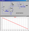
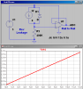
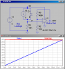
Here is my photodiode and op-amp, as well as a basic idea of the circuit:
( sfh2505 )
LM2902KDR Texas Instruments Op Amps
https://www.aptechnologies.co.uk/PDF/Photodiode%20Typical%20Circuits.pdf
My concern is choosing the value of the resistor. I chose 30K based on something I read online about these circuits. The idea is I want a LOW output when it's in ambient light and HIGH when it's directly in sunlight. I have a direct relationship between solar lux and photocurrent Ip from the data sheet, and from wikipedia, I know my range of lux (for morning balloon launches) will be about 400 for sunrise to 10-25,000 for overcast midday and 125,000 full sunshine at noon.
Combining these two facts, my range of Ip will roughly be about .04mA - 12.5mA for sunrise - full sunshine @ noon. Now, I will need to amplify the output since this is small, so it can be read by the Arduino.
I will (hopefully) be outputting to an Arduino ('Freeduino' actually) microprocessor board (recommended input 7 - 12 V). I will also pull 5V directly from the Arduino to supply the reverse bias voltage Vr. In addition I was thinking of adding two capacitors onto the top and bottom of the op-amp to reduce noise.
Any suggestions/help would be great! Thanks
Here is my photodiode and op-amp, as well as a basic idea of the circuit:
( sfh2505 )
LM2902KDR Texas Instruments Op Amps
https://www.aptechnologies.co.uk/PDF/Photodiode%20Typical%20Circuits.pdf