Hello,
I am having problem with fixing Philips 288P6LJEB/27 monitor PSU, board number 715G6457-P01-000-0010.
Data:
- Schematic is attached to post
- Photos can be found on flicker: https://www.flickr.com/photos/198547898@N03
Problem:
- PSU board have power outputs at 5.2V, 12V and 24V - board is correctly outputting only 5.2V (correct), and not 12V (without load only 8.16V) or 24V (without load 0V)
State of PCB / monitor:
- Bought defect monitor from a company auction
- There were some attempts to fix the monitor, as I saw a changed capacitor and screwdriver marks on the enclosure.
Troubleshooting steps:
- There is no short to ground from 12V (approx 3kOhm) or 24V (approx 3kOhm) - I guess there is no problem on the low voltage side
- Vsin after full bridge rectifier looks OK (325V DC with DMM) - I guess nothing wrong until after full bridge, marker Vsin in schematics
- Some voltage regulation works:
- Voltage on 12V rail says approx the same after applying 230Ohm resistor to ground (8.16V before, 8.10V after)
- Checked all diodes with DMM (all diode voltages looked OK), checked all capacitors for shorts, checked all resistors (all resistance looked OK). I am not 100% sure I did not miss some OR I measured wrongly.
Troubleshooting actions:
- Replaced STF24NM60N Q9801, as it looked damaged (nothing changed)
- Replaced C9807 (nothing changed)
First guess for the problem:
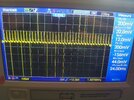
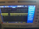
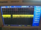
- problem in current sensing circuit for SSC1S311 IC (VCC marker in datasheet - without load DC=13V, AC=0.26V, with load DC=16V AC=0.012).
While I have some knowledge about electronics, I don't know how Quasi-Resonant Off-Line Switching Controllers (SSC1S311) work, so got to the knowledge wall I can not pass, as I can not pinpoint which part of the circuit is faulty.
Any ideas about what could be wrong - feel free to share, because I am out of them
Thank you in advance for all your answers,
Gregor


