Continue to Site

Welcome to our site!

Electro Tech is an online community (with over 170,000 members) who enjoy talking about and building electronic circuits, projects and gadgets. To participate you need to register. Registration is free. Click here to register now.

  • Welcome to our site! Electro Tech is an online community (with over 170,000 members) who enjoy talking about and building electronic circuits, projects and gadgets. To participate you need to register. Registration is free. Click here to register now.

Phasor Difference?

Status
Not open for further replies.

codan

New Member
Hi Everyone,

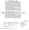
I need to find the "phasor difference" between two voltages of the same value & differing in phase by 60deg?

I am unsure if that means the phasor difference between the two voltages themselves or the two voltages in relation to a 0 reference line or neither?
To be honest i am not sure about this as i have only done phasor addition etc.

The only information i have is that the "phasor difference" is the unknown side of a parallelogram developed from one side and the diagonal?.

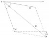
I have taken a stab at it in the attachment below, i first worked out the resultant (Vtotal) of the two voltages as you'll see & then added what i think the phasor difference is (in this case 10deg) but this seems to be in relation to the 0 ref line--no idea?

I need some advice on this one?

Thank You
 

Attachments

  • Phasor Difference.jpg
    Phasor Difference.jpg
    21.6 KB · Views: 389
Last edited:
I'm not familiar with the term "phasor difference".

I assume it means the voltage difference between 2 voltages that are not in phase.

ie. V1 - V2.

If so, you would draw a line 180 degrees out of phase with V2 (ie. -V2) and then add it to V1.
 
Hi Len,

I have attached a couple of phasor drawings that i think are what you mentioned.

I am a little--well a lot confused about this Phasor Difference.

The Voltages V1 & V2 = 240V & the result from the method mentioned (if i have it correct) & the scale i am using also is 240V so i am not sure if i have done this correct or if the Phasor Difference is supposed to be in Degrees of the resultant angle which is 60deg but this is the original phase angle?

Thank You
 

Attachments

  • Phasors.jpg
    Phasors.jpg
    15.9 KB · Views: 371
Last edited:
Can you type out the question exactly as it was given to you and provide any diagrams? At the moment I don't understand the question.

Mike.
 
Hi Mike,

The original question is:

Find the phasor difference of two voltages having rms values of 240v & differing in phase by 60deg. Use a scale of 20mm=40v

No Diagrams supplied.

Thank You
 
Last edited:
The question is vague. As I said, "phasor difference" is meaning less to me.

However, what the question appears to be asking is:- find V1 - V2.

So you have done the diagrams correctly.

The answer is 240 Volt with the resultant leading by an angle of 60 degrees as you have drawn.

(I checked it using complex numbers)
 
Thanks Len,

I understand what you mean about the question being vague & the meaning of Phasor Difference.

I thought the previous attachment was phasor subtraction which is throwing me off.

I don't mean to be a pain in the butt & i certainly don't want to waste peoples time but can we look at this in a different way just for a moment.

I have attached three diagrams on one sheet, the first diagram is the original attachment No1, the second is for (V1 NOT KNOWN) so to find V1 & the Phasor Difference in respect to 0 Ref.
The third diagram is (V2 NOT KNOWN) so to find V2 & the Phaser Difference in respect of 0 Ref.

The question says, find the phasor differences of two voltages, could this mean "individually" in respect of 0 Ref as i have tried to do in the attachment.

Are my diagrams correct for finding the "unknown values mentioned & the phasor difference" in respect to 0 Ref, if in fact that is what Phasor difference means, or am i way out?

You'll have to shoot me, as i find this interesting Haha!
Thank You
 

Attachments

  • Phasor-3.jpg
    Phasor-3.jpg
    38.7 KB · Views: 364
I don't want to be a pain in the bum either, but I really don't know.

Your diagrams 1 & 2 are Vt = V1 + V2

In 3 you have related the phase to the 0 line which is chaosen randomly. This does not make any sense to me.

Perhaps you're trying too hard to decipher the meaning of "phasor difference"

As far as I can see, it means V1 - V2 or V2 - V1.
 
Last edited:
Hi.
To make math between out-of-phase phasors, you need to project each phasor to the bases.
For example:
You know that the both phasors are dephased by 60º. So it doesn't hurt to make V1 = 0° and V2 = -60°.

But what is V1?
V1 is V1*cos(0°)i + V1*sen(0°)j. -> That means: V1*cos(0°) on base "i" and V1*sen(0º) on base "j".

And V2?
V2 is V2*cos(-60°)i + V2*sen(-60°)j.

Which takes us to V1 - V2 = (V1 - V2*cos(-60°))i + (0 - V2*sen(-60°))j

To find the magnitude again, just use the Phytagoras theorem.
 
Hi Len,

Yes, i guess your right i have been trying to decipher Phasor Difference a bit, i just thought i had better understand what it actually meant before trying to answer it if you get my drift.

Unfortunately i don't have all the related material from the course as i have just a copy of the questions from a friend of the family who is doing the actual course full time, because i am to young to get the course proper & they wouldn't let me tackle it.
Once i complete this though i will try to get enrolled again showing what i have done from the paper work i have recieved & that may change there mind & let me do it properly.
At the moment it's all study & trying to understand things so i can complete a trade when i am of age.

I will go & ask if there is any related paperwork regarding this & see if i can get a copy & post it.

Thanks very much for your time.

Hayato

Thanks for the equations regarding this they will be helpful, i don't mean to sound ignorant but i am not sure what "sen" is?
Did you mean sin or is there a sen as well ?

Thank You
 
My bad, it was a sin to write sen instead of sin. =D.

If you have doubts, always decompose your vectors to the base and do the operations there. And remember that bases are always orthogonal, in a scalar multiplication that means:
(Ai + Bj) . (Ci + Dj) = A.Ci + B.Dj
the terms (A.D)i.j , (B.C)i.j are 0, because i.j = 0

It is not correct to use vectors for electrical calculations.

In electrics, we use complex numbers.

for example (a + jb) x (c + jd) = ac - bd +j(ad + bc)
 
I see no problems in treating complex numbers as vectors, as long as you respect the complex math rules.

In fact, in the past, complex math was done in vectorial way. to make things easier.
 
this is my take. The resultant of a subtraction is drawn between the short diagonal of the parallelogram. This is the same as tail to tail of phasors which compares to head to tail for addition.


**broken link removed**
 
Last edited:
I see no problems in treating complex numbers as vectors, as long as you respect the complex math rules.

In fact, in the past, complex math was done in vectorial way. to make things easier.

You can use vectors to add or subtract phasors, but not for multiplication or division as I showed in my previous post.

The scalar product and vector product are not valid for complex numbers.
 
Hi Everyone,

I have just returned from a library where i found the elusive Phasor Difference-- I think!

Anyway i copied a part of a page that suggests what it is, i'll attach it.

So does this mean that the Phasor Difference is in fact the 240v resultant we had before, i'll attach it again?

Thank You
 

Attachments

  • Phasor Difference.jpg
    Phasor Difference.jpg
    45 KB · Views: 343
  • Phasors.jpg
    Phasors.jpg
    15.9 KB · Views: 298
Hi mel8030


Thanks for the diagram, i have been told three times now to reference one phasor at 0 deg so i guess i should listen & do it correctly.

The phasor subtraction from your diagram gives the same result as the other method Len suggested, so i guess there is more than one way to skin a cat.

I found a phasor subtraction method, like the one i used before as suggested, i'll attach it.

Now everyone,
In the attachment they haven't referenced one phasor to 0 zero--how come if that is the correct method?

Now the big one, what is the difference between a Phasor & a Vector seeing now that Vectors have been mentioned?

Thank You
 

Attachments

  • Phasor subtraction.jpg
    Phasor subtraction.jpg
    57 KB · Views: 394
They are showing the general case.

The 0 reference line would be some other phasor as there is no point in drawing it this way if there are only 2 phasors involved.

Vectors. An example from Physics is the resultant of forces acting on a body.

For example, say you had a round, flat concrete slab laying on a horizontal surface.

If you applied a 1 kg force to it pointing north, it would start to slide northwards.

But if you then also applied a 1 kg force to it pointing west, the slab would slide NW since the resultant is at 45 degrees to both forces.

You can use the same diagram as you did for the phasors to calculate the magnitude & direction of the resultant force.

Phasors are similar to vectors, and you can (as our friend from Brazil pointed out) use vector algebra to calculate the sum and difference of phasors.
 
Status
Not open for further replies.

New Articles From Microcontroller Tips

Back
Top