Continue to Site

Welcome to our site!

Electro Tech is an online community (with over 170,000 members) who enjoy talking about and building electronic circuits, projects and gadgets. To participate you need to register. Registration is free. Click here to register now.

  • Welcome to our site! Electro Tech is an online community (with over 170,000 members) who enjoy talking about and building electronic circuits, projects and gadgets. To participate you need to register. Registration is free. Click here to register now.

pH sensor

Status
Not open for further replies.
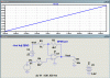
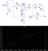
I have MCP607. I even tried to built it my adding the voltages at the initial stages. Here is the new schematic attached. I gives 600mv at 0mv input. But at the extreme it fails like +413 should give 100mv and -413 mv should give 1100.

Their is the differene of 50mv on both side.

hi,
Looked at your drawing, where did you connect the probe.?

Also would a minimum pH of 2 thru to 14 be acceptable.?
 
hi,
Look at this option, just shows the basic circuit.:)

The -Vref should be derived from a voltage reference and be adjustable.

Note: for the MCP607 the recommended -Vsig is -0.3V [not -0.413V], so there is a minimum pH signal limit.
If you used a CA3140 opa this would allow a -0.5V input.
 

Attachments

  • pH01.gif
    pH01.gif
    24.2 KB · Views: 227
I went back to the first post to see what this was for. I found this.

I also went thru the posts and found this

I do have such solutions capsules of 4,7,10 pH. But what should be the actual calibration steps.
Do i need to change the gain value as time passes or some other method??
 
Looked at your drawing, where did you connect the probe.?

The probes would be connected at the V points. The refernce electrode at V1 pin and the measuring electrode at the V2 point.
 
My understanding is that the input span is -413mV to +413mV, and the output span needs to be 100mV to 1100mV. Below is a circuit that should do this. Op amps need to have CMOS inputs.
 

Attachments

  • pH sensor amplifier.PNG
    pH sensor amplifier.PNG
    31.3 KB · Views: 270
Last edited:
hi Ron,

Are you saying that you want to shift the -413mV thru +413mV input range to, 0V thru +826mV or 0V thru +5V.???

yes i that to do that. Need help for the schematic

I guess we will have to see what the OP finally decides upon.:)

BTW:
For ref only, you may have this already, if so please ignore.
Circuit Collection
 
Status
Not open for further replies.

Latest threads

New Articles From Microcontroller Tips

Back
Top