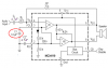
It works fairly well when the gain is high. The 1st amp has a gain of 26, and the 2nd amp has a gain of only 24 which isn't too bad a difference.Nigel Goodwin said:Isn't the internal circuit of the chip wrong as well?, the input is shown connected to the non-inverting input of BOTH amps.
If the gain was only 1 then the 2nd amp wouldn't have any output.
Actually, with a gain of one then the output of the 2nd amp would be only the distortion products of the 1st amp.
The amp can be setup with an inverting input and with a low input impedance. Then the output level from each amp is the same.
I don't like the 2nd amp amplifying the distortion from the 1st amp, but it sounds OK with its very high amount of negative feedback cancelling the distortion. :lol:
 80 watts!!!!!!