Electro Tech is an online community (with over 170,000 members) who enjoy talking about and building electronic circuits, projects and gadgets. To participate you need to register. Registration is free. Click here to register now.
Welcome to our site! Electro Tech is an online community (with over 170,000 members) who enjoy talking about and building electronic circuits, projects and gadgets. To participate you need to register. Registration is free. Click here to register now.
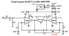
As are the vast majority of transistor audio power amplifiers. The circuit you posted actually uses two amplifiers in a bridged configuration, to give twice the power to twice the impedance of a single amplifier.
will this circuit work?
i'll start working on it from tomorrow
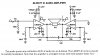
It's done because the decoupling effect of the large electrolytics will be less at higher frequencies, so adding a small non-electrolytic capacitor in parallel can improve decoupling at high frequencies.
The LM3875 is an excellent audio amp IC. Look at its product folder: **broken link removed**
In the folder is a link to its datasheet that you should have. It has details about heatsinks and stuff. :lol:
dual power supply
how will i check my project at home?
i hav a dual power supply in univesity...
not at home....
ne shortcuts?
or how do i design a +-25 volt power supply?
Why use shortcuts when building an excellent power amplifier?
If its supply was a single polarity the the amp would need the problems of a huge output coupling capacitor.
Wait a minute! This is a bridged amp. It will work fine without an output coupling cap if you properly bias the inputs so it can use a single +50V supply. It might have a pretty big "bang" when it is turned on or off unless you plan to have its input coupling cap charge and discharge slowly.
I started reading all the artilces and comments about these "Gainclone" amps on the web. Some are hillarious.
ok..i am making a dual power supply for it too
it'll earn me more marks
i found a schematic for it
if tht output is less than 25 say...23 or 22..will by power amp work?
or should i make a supply with a wider range? say till + - 35?
how can this one be improvised?
using a higer rating transformer?
ne other changes?
ok..i am making a dual power supply for it too
it'll earn me more marks
i made a dual power supply before....but..it is 15 to -15 volts
any way of improving it so tht it could work from +25 to -25?
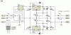
You only need a very basic supply, just a center tapped transformer, something like 18-0-18 (bit too high) or 15-0-15 (bit too low), a bridge rectifer, and two large electrolytics.
You must plan the entire design of a power supply, not just its voltage.
The datasheet shows that with a 50V supply, two bridged LM3875 ICs driving 80W into an 8 ohm load causes the amps to heat with a total of 66W. That heat must be dissipated by a huge heatsink.
Since 66W must be dissipated as heat and an additonal 80W is dissipated by the load then the total power from the power supply is 146W.
Simple arithmatic shows a power supply current of 2.92A which is way higher than the max from the little regulators in the power supply circuit you found.
Why use regulators? They aren't needed with a huge 37V/4A transformer and 10,000uF of filtering. The amp won't be operating at max power continuously so a 2A or 3A transformer will be OK. Double its current for stereo.
The circuit will drive an 8 ohm speaker to 60W with a 15V-0-15V transformer and the supply current will be 2.4A max. A 50VA to 100VA (1.7A to 3.33A) transformer would be fine.
but...but...i counldnt find the IC LM3875 so tht project is no more
now am looking for something else to submit to my professor
10 watt amp or a 20 watt amp....easy to make as i dont hav much time left saturday is the date for submission
This site uses cookies to help personalise content, tailor your experience and to keep you logged in if you register.
By continuing to use this site, you are consenting to our use of cookies.

")