Hi, brand new here.. really hope i can get some assistance.
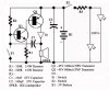
Aight... basically, I messed about for the year and didnt learn as much as I should have. Have had to do a project designing a circuit for a personal alarm. I found the personal alarm circuit design online and added 2 led's to the circuit for the torch.
I then added 2 components (a resistor to limit the voltage to the led's & a diode to protect the oscillator) but i dont know what type they have to be.
If any1 has any knowledge on this and can help me it would be appreciated as I need to do this to pass my course.
(Excuse the old resistor symbols but thats what we were taught).
Complementary transistor-pair is wired as a high efficiency oscillator, directly driving a small loudspeaker
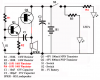