Electro Tech is an online community (with over 170,000 members) who enjoy talking about and building electronic circuits, projects and gadgets. To participate you need to register. Registration is free. Click here to register now.
Welcome to our site! Electro Tech is an online community (with over 170,000 members) who enjoy talking about and building electronic circuits, projects and gadgets. To participate you need to register. Registration is free. Click here to register now.
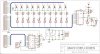
The original Oriental circuit uses the LM3914 with its outputs set to 12.5mA directly driving the cathodes of the LEDs. 2N3906 transistors driving the anodes of the LEDs will be fine with such a low current.
But multiplexing reduces the average current in the LEDs to only 1.25mA so they will appear extremely dim. Many things need to be changed to increase the current.
The LM3916 is a VU meter LED driver. The input voltage step spacings are all different.
The LM3915 is a logarithmic LED driver. Each input voltage step is 3dB more than the LED below it.
The LM3914 is a linear LED driver. Each step is 10% higher voltage than the LED below it as a voltmeter.
All three LED drivers have a max output current of about 25ma which is nice and bright without multiplexing.
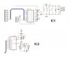
Thanks by the data, Audioguru. I got the board etching done, but before go shopping I'm worried about this Eagle's warning (don't laugh)
WARNING: Sheet 1/1: POWER Pin IC2P VSS connected to GND
WARNING: Sheet 1/1: POWER Pin IC2P VDD connected to VCC
Vss must be 0v, so what's the problem connecting it to gnd? should the oriental circuit be redesigned??
WARNING: Sheet 1/1: POWER Pin IC1P V+ connected to VCC
WARNING: Sheet 1/1: POWER Pin IC1P V- connected to GND
another thing, according to datasheets the LM3914 and LM3915 share the same pinout, but could be used indistinctly with the oriental circuit? (I prefer the shame of asking, instead of blowing the money up)
I have been working with this circuit as ewell as tghe vellman circuit.
the vellman uses bi lateral switches instead of transistors.
the bargraph driver (3914,15,16) needs some help as the leds will be too dim.
Audioguru and I have been throwing out stuff right and left.
getting down to maybe something that works.
will keep yopu posted or you can add to the discussion, the more the merriery
The LM3914 is a linear voltmeter. Each step is 10%.
The LM3915 is a logarithmic sound level or audio power meter. Each step is 3dB.
The LM3916 is a VU meter. Each step is different.
They all have the same pins. They are designed to directly drive 10 LEDs, Extra transistors are needed if the outputs are multiplexed.
This site uses cookies to help personalise content, tailor your experience and to keep you logged in if you register.
By continuing to use this site, you are consenting to our use of cookies.