Continue to Site

Welcome to our site!

Electro Tech is an online community (with over 170,000 members) who enjoy talking about and building electronic circuits, projects and gadgets. To participate you need to register. Registration is free. Click here to register now.

  • Welcome to our site! Electro Tech is an online community (with over 170,000 members) who enjoy talking about and building electronic circuits, projects and gadgets. To participate you need to register. Registration is free. Click here to register now.

Peak detector for VU meter

Status
Not open for further replies.

caution

New Member
I'm looking for a little bit of help with a circuit I'm building to drive some LEDs for a VU meter project going into a JVC M70 radio. Actually I'm using the ones already there for a different function, and moving the old signals to new LEDs behind the originals so they can still shine through.

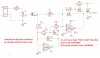
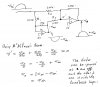
I finished that part and began to install some LM3915 kit boards when I realized they didn't work at all, so I had to wire up my own circuit. After getting some LM3916s with the semi-log audio stepping and getting it running with all 10 LEDs on a test setup, I determined it has to have peak detection to look decent, so I tried the half-wave peak detector in the datasheet notes.

From what I can tell, the forward bias of the diode across the 2N3906 ruins the first 0.7V of my line-level (1.2V?) audio signal, so the first 4-5 LEDs are always on. I thought about using the headphone output to get more oomph, but I don't want the meters to vary with actual volume, as some models out there do.

I almost decided to live with the first few LEDs being unusable on the half-wave peak detector because I only have 6 LEDs per channel (actually there's 5, but I'm OR-ing an 11th, center LED with the first LED from each channel), but that doesn't really look right because although you have five LEDs in a row at the top end (+3/+2/+1/0/-1 dB) it doesn't even respond to half of the audio you hear, so I need to have at least the first LED (-20 dB) and probably the third (-7 dB) to look right.

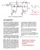
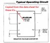
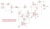
So, I breadboarded the precision full-wave peak detector. I tried using the TL082, since it was available in the stores and is what seems to be a good-enough version of the TL072, which I've seen referred to as an equivalent to an LF353, which is what the example uses in the LM3916 datasheet. This circuit, after building it a few times, turns on the LEDs solid. My knowledge of op amps has me against a wall. I'm using precision resistors, so that's not an issue.

From what I can find, these op amps (LF353/TL072/TL082) cannot function unless there is at least 3.3, preferably 5 volts on the negative rail. If this is true, what can I do? My lowest level in the radio is ground. Can I do something with another TL082 to shift the signal down some?
 
Re your last para. No, that is not true. You can make Op Amps work with a single supply voltage. It is purely a matter of setting the inputs at the DC correct levels.

Post your circuit so we can see what you're doing. Otherwise, we are working in the dark.
 
I don't have it captured in a tool, if that's what you need specifically. Perhaps for now if it helps, this circuit (**broken link removed**) from another user here shows what I first wired up, and now I've replaced the audio input stuff into pin 5 with what's in this image (**broken link removed**). I'm using a 7809 regulator powered off 15V main power.
 
I ahve attached an item copied from a National Semiconductor (NS) book that was published in 1970. It explains how the rectifier circuit works.

The one you posted is based on this but it has 2 half wave rectifiers (HWR) in tandem to produce a full wave result.

The NS one is simpler as it uses a summing Amp in lieu of the second HWR as in your version.

The summing amp also does the filtering to give a DC level output.

In order to use only one supply, you will need a "Rail to Rail" Op Amp such as the LMC6482. This a Dual package. The Quad version is the LMC6484. Both are sold by JayCar.

I'll study the NS article later today & show you how to make it work with a single supply voltage.
 

Attachments

  • Full Wave Rectifier.jpg
    Full Wave Rectifier.jpg
    1.2 MB · Views: 1,468
Here are my suggestions:-
1. You can replace the TL082 with a LMC6482. (You should compare their pin number as there may be some differences)
2. Alter your circuit to use the NS circuit that I posted above. The resistors can be 10 times the values shown in the NS circuit & the capacitors can be one tenth of those in the NS circuit. See the attachment FW Rectifier.
3. Use a Positive to Negative DC Converter as shown in the Pos to Neg attachment & thereby use your existing circuit with the TL082 ICs.

I suggest that you look at this https://www.electro-tech-online.com/threads/basic-opamp-circuits.35258/ if you have not already done so.
 

Attachments

  • FW Rectifier.jpg
    FW Rectifier.jpg
    609 KB · Views: 1,765
  • Pos to Neg Converter.jpg
    Pos to Neg Converter.jpg
    108.1 KB · Views: 543
Last edited:
I'll see what I can do about locating those chips. Thanks so much for the insight.

Today I found what might be my simplest answer. I'm almost done wiring it up. Someone solved the same problem by tieing the noninverting inputs high on the peak detector, added a zener diode, and added a second op amp ahead of it to amplify the incoming signal, which I believe I should be doing. The schematic I'm following is **broken link removed**.
 
You could also do a simple & cheap Pos to Neg converter using a 555 timer operating as an oscillator with 2 diodes & 2 capacitors (to produce the neg voltage). You may be able to find a suitable circuit on one of the numerous 555 sites. If not, can draw & post one for you.
 
Your half-wave peak detector with the 2N3906 transistor did not work properly because the datasheet says it is designed for a 10V peak signal so that the base-emitter of the transistor and the diode almost cancel. It works as low as when the input level is about 450mV which lights the first LED of an LM3915.

The full-wave peak detectors need the opamps to have an additional negative supply, or have the opamps biased at half the supply voltage and input and output coupling capacitors added.
 
I'll see what I can do about locating those chips. Thanks so much for the insight.

Today I found what might be my simplest answer. I'm almost done wiring it up. Someone solved the same problem by tieing the noninverting inputs high on the peak detector, added a zener diode, and added a second op amp ahead of it to amplify the incoming signal, which I believe I should be doing. The schematic I'm following is **broken link removed**.
I missed this post. Yes, Fig 11 is another way of doing it with the Op Amps that you have already.
 
This is kind of crude, but I think it will work.
It divides your 1.2 volts down to below .3 volts because the 339 ESD diodes will clamp at about - .3 volts.
You could also use a common op amp like the LM358 or 324 that can sense at ground, but they have a little trouble at 20 KHz.
You should be able to find the 339 easily.
 

Attachments

  • peak detect.png
    peak detect.png
    166.8 KB · Views: 534
Last edited:
Your half-wave peak detector with the 2N3906 transistor did not work properly because the datasheet says it is designed for a 10V peak signal so that the base-emitter of the transistor and the diode almost cancel. It works as low as when the input level is about 450mV which lights the first LED of an LM3915.

The full-wave peak detectors need the opamps to have an additional negative supply, or have the opamps biased at half the supply voltage and input and output coupling capacitors added.
Audio, I don't agree that you need a neg supply or to bias the Op Amps @ half Vcc if you use Rail to Rail Op Amps as I suggested in post #5. What put me off the half Vcc option was that you would need level shifting (& therefore another Op Amp) in order to provide the LM what-ever-it-is a 0 Volt input when the AC input is 0. What are your thoughts on these issues?
 
This is what I used;
**broken link removed**
With slight modification I made it do peak hold as well.
 
Audio, I don't agree that you need a neg supply or to bias the Op Amps @ half Vcc if you use Rail to Rail Op Amps as I suggested in post #5. What put me off the half Vcc option was that you would need level shifting (& therefore another Op Amp) in order to provide the LM what-ever-it-is a 0 Volt input when the AC input is 0. What are your thoughts on these issues?
When the input goes positive then the output of the first opamp must go negative so that its series diode pulls the inverting input of the second opamp negative. Then it needs a negative supply.

All my Vu meters are half-wave and work fine. Our vision sees 30ms durations at full brightness so I do not hold longer than 30ms.
Yes, you're right except the part I highlighted in red needs some qualification.

The Pin 1 of IC2A must go sufficiently negative until pin 2 is at 0 Volt (due to the negative feedback). Thus pin 1 goes negative as the input goes positive in order to keep pin 2 at 0 Volt. So IC2A is acting as a unity gain inverter for positive inputs. See attachment.
 

Attachments

  • FWR.jpg
    FWR.jpg
    480.9 KB · Views: 482
It just occured to me that the Diodes D3 & D4 do nothing in the circuit posted by the Op.

When you remove them, the circuit reduces to the one I posted in post #5 that came from the NS book.

Also, Capacitor C5 can be moved to the feedback circuit as in the NS circuit & R6 is unnecesary. See the attachment.
 

Attachments

  • FW Rectifier 1.jpg
    FW Rectifier 1.jpg
    502 KB · Views: 429
Of course when the input goes positive, the negative output of the first inverting opamp must provide the same current in the output diode as the negative feedback current in the second opamp plus the input current ion the 200k resistor so that they cancel.
 
A peak detector is supposed to have a very fast attach and a slow release that cannot happen if the second opamp has a capacitor across its negative feedback resistor.
 
Of course when the input goes positive, the negative output of the first inverting opamp must provide the same current in the output diode as the negative feedback current in the second opamp plus the input current ion the 200k resistor so that they cancel.
Agreed. That's what the maths in my post #16 shows.
 
Status
Not open for further replies.

New Articles From Microcontroller Tips

Back
Top