Continue to Site

Welcome to our site!

Electro Tech is an online community (with over 170,000 members) who enjoy talking about and building electronic circuits, projects and gadgets. To participate you need to register. Registration is free. Click here to register now.

  • Welcome to our site! Electro Tech is an online community (with over 170,000 members) who enjoy talking about and building electronic circuits, projects and gadgets. To participate you need to register. Registration is free. Click here to register now.

PCB track burning

Status
Not open for further replies.

mone

New Member
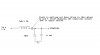
24 vol is given to the in inductor of 7uH/1.2A which is in series with the parallel plate capacitors of 10uf/50v(polarised capacitor) and 0.1uf(smd capacitor).Both the other end legs of capacitor are shorted to ground .All together,inductance,and parallel capacitors that is in series with inductor are going to the input pin of LM2506 ic.Now my track is getting burnt in the area between the inductor and parallel capacitors.there is a voltage drop happening in 10uf capacitor.on wat value of capacitor,volatge dont drop or should i've to reagrrange the circuit.I donknow how to attach the image else i cud draw the crcuit.Please help me.**broken link removed**
 
plz help me in uplaoding.I seriously tried inserting image n it asked to enter the url ...after i typed the url,nothing is visible...
 
Look at the LM2506 data sheet for the max input voltage ... 24V is way too much, and it's probably drawing LOT'S of current.
 
plz help me in uplaoding.I seriously tried inserting image n it asked to enter the url ...after i typed the url,nothing is visible...

Step by step operation.
 

Attachments

  • a.gif
    a.gif
    9 KB · Views: 192
  • b.gif
    b.gif
    13.8 KB · Views: 184
  • c.gif
    c.gif
    6.2 KB · Views: 191
chk my circuit

plz look into circuit and let me know either i've to change the capacitor or the inductors current rating or any resistor near the IC?
 
it can take up to max voltage of 40 and min is 37 i guess....either i've to change teh current rating of my inductor or replace with some other capacitor as i find there is voltage drop else i've to thicken the track but thickeing the track is teh temproray adjustment.i've posted the circuit.Chk up...
 
We had the same problem. It just the heat generated by the inductor. Put a length of tined copper wire along the track and next time increase the width of the track.
 
increasing the width of the track is not the proper solution..may be it 'll be effective but watz d percentage of improvement ??......any test case after thickening the track??...i mean how to chk the tolerance????
 
The track is acting as a heat dissipater. The exact solution is to increase the width to improve the thermal dissipation. That's why you are asking the experts to help you.
 
It's not a tank circuit. It's an LC filter. You can change the L for a resistor but you will drop more voltage to get the same filtering effect. The inductor is much more efficient than a resistor in this type of circuit.
 
yeah am clear to wat you say.can i give a try by replacing the capacitor 10uf to some other value??..
 
to be open ,this problem is happening very recently...some thing else is hindering my circuit.
 
i wanted to measure the current consumption on my pcb in power supply connecter.I connected one input wire 1 to the positive of multimetr and input wire 2 to the connecter where i need to measure and i kept the multimeter on the other end of the connector where input wire 2 is connectedr . bt am not finding anything to happen.am i measuring current in a wrong way??please tell me how to measure???
 
Status
Not open for further replies.

Latest threads

New Articles From Microcontroller Tips

Back
Top