Continue to Site

Welcome to our site!

Electro Tech is an online community (with over 170,000 members) who enjoy talking about and building electronic circuits, projects and gadgets. To participate you need to register. Registration is free. Click here to register now.

  • Welcome to our site! Electro Tech is an online community (with over 170,000 members) who enjoy talking about and building electronic circuits, projects and gadgets. To participate you need to register. Registration is free. Click here to register now.

Pcb design help

Status
Not open for further replies.

Doomguy42

Member
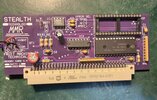
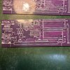
I've I've recently built my first pcb in express pcb. It was reasonably expensive to get the gerbers but I went ahead and was very happy with my board.

I was recommended easy EDA to try but looking at it it seems you have to start a build with a schematic design? Or is there a physical board design like expresspcb?
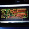
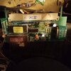
What I'm doing is reverse engineering a big damaged old 90s arcade board I don't have a schematic to work from. I can physically remake a board much easier than build a whole schematic so I'm looking for some software that's right for me if anyone can help? Just looking for the CAD PCB side not a schematic
Few pics of my first attempt remake project (small size looking to do the same but a much bigger board)
 

Attachments

  • 20221022_122703605.jpg
    20221022_122703605.jpg
    1.5 MB · Views: 133
  • 20220726_193120661.jpg
    20220726_193120661.jpg
    2 MB · Views: 134
  • 20220706_204616361.jpg
    20220706_204616361.jpg
    1.9 MB · Views: 138
  • 20220629_212309175.jpg
    20220629_212309175.jpg
    1.2 MB · Views: 131
Most PCB software will allow you to create just a PCB, without a circuit - but it's a pretty bad idea.

Trace the circuit from the old board and create your own circuit diagram, then create a PCB design from that.

But if you want to try just a PCB?, then DesignSpark (free from RS Components) will allow either or both, as will most others.
 
I've designed quite complicated boards without a schematic. However I have also made mistakes in some quite complicated boards. Now I will always try to have a schematic, even if it is drawn after a lot of the layout is complete. The PCB software can check that a layout and a schematic agree with each other, and it is a lot easier to check on a schematic that wires go where required.

There are some extra constraints that need to be followed when getting the software to compare the schematic with the layout. In many circuits that are connections or gates that can be swapped, and PCB software like DesignSpark won't accept the swaps, so extra work is needed to get the checks to pass.

Examples of swaps that usually make no difference are:-
Which way round passive components are fitted.
Which inputs of simple gates go where, like dual-input NAND gates, or inputs of bridge rectifiers.
Which gate or amplifier or whatever in a multi-gate package is used.
On microprocessors, many pins have multiple functions, and can be interchanged and sorted in software.

Also the schematic may not show you anything about physical layout, so you need to separately check rules like keeping decoupling capacitor close to ICs, keep ground wires short and clearances where high voltages are used,
 
Status
Not open for further replies.

Latest threads

New Articles From Microcontroller Tips

Back
Top