Continue to Site

Welcome to our site!

Electro Tech is an online community (with over 170,000 members) who enjoy talking about and building electronic circuits, projects and gadgets. To participate you need to register. Registration is free. Click here to register now.

  • Welcome to our site! Electro Tech is an online community (with over 170,000 members) who enjoy talking about and building electronic circuits, projects and gadgets. To participate you need to register. Registration is free. Click here to register now.

Particular use of a MOSFET

Status
Not open for further replies.

DerStrom8

Super Moderator
Hi all,

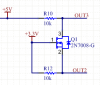
I recently came across the following configuration for a MOSFET:

broken link removed

OUT3 and OUT2 are simply output BNC connectors. Is the MOSFET only being used for its diode? Or is something fancier going on here?

I have never seen a MOSFET used this way, but I'm hoping someone else has.

Thanks,
Matt
 

Attachments

  • upload_2015-7-23_9-4-9.png
    upload_2015-7-23_9-4-9.png
    10.5 KB · Views: 147
Last edited by a moderator:
RDS(on) appears to be uncharacteristically high (7.5Ω) for a mosfet?, Maybe making it a constant current source as in a diode, it does have very low Vgs however.
OUT2 & 3 are power source derived, with just his info there does not appear to be data imposed on either.
Max.
 
Q1 would act like a source follower.
It would appear that its purpose is to level translate the 5v to 3.3V at OUT2, which would only work if the transistor threshold voltage is near 0V.
But the 2N7008 has a Vgs(th) of 1v-2.5V so the worst-case, open-circuit output would be 0.8V, likely not the intended output.
 
The GS voltage seems held at 3.3v so it should always be in conduction, no?
I am wondering if that Rds (on) is a misprint?
Max.
 
I think an older version of this design used the BSS138, which has a maximum threshold voltage of 1.5v. I wonder if the change to the 2N7008 was a mistake...
 
It's a level shifter. Here are some useful links:

Microchip:
https://ww1.microchip.com/downloads/en/DeviceDoc/chapter 8.pdf

TI:
**broken link removed**

Philips (secondary site):
https://www.adafruit.com/datasheets/an97055.pdf

John

Thanks John. Yep, I had come across that before and I'm pretty sure that's exactly what it's being used for. I just looked at a different schematic sheet in this design and found that OUT2 is coming from an FPGA board, passed through a buffer, then into the circuit shown. I'm not familiar with level shifters but I'm going to do some reading.

Thanks,
Matt
 
You guys are awesome, thanks for the help! A level shifter is exactly what it is! OUT3 drives a 5V device, but the logic comes from an FPGA board with a 3.3V output (OUT2).

Cheers,
Matt
 
I asked the same question on AAC heh heh. But; I'm just wondering if the same logic is used on SDI video switchers?

kv

Edit: I know it should be something similar but; not sure if it's all together different or not?

Ok, found something on it. SDI Video 10 things I didn't know about it. LOL
 
Last edited:
Ooooh! A mosfet only application..... Like I said BJT's have their place as do fet's..

I wouldn't know the difference; I only know about the equipment we use; which was standard def AV. But; since we began to broadcast over IP and the introduction of Digital signals I'm trying for a network certification and don't know if these 0's and 1's are similar and digital is digital just at different speeds and purposes.

kv
 
You had to be there.;)
I had suggested a better alternative to a Bipolar in an application and apparently it hit a sore point!.
Max.

I'm off work; but still no time to google for and understanding on how this stuff works together. But; I did just find this broken link removed

Looks like this is just stuff for Micro controllers and UC's. First time on this site I was trying to understand pull-up and pull-down resistors; this is helping a little now because this URL is on TTL which I'm sort of understanding.

I'm just over my head as a hobby guy. Maybe once I get to play with Micro's I'll learn enough that it will eventually make sense.

Thanks Max.

kv
 
Last edited by a moderator:
. First time on this site I was trying to understand pull-up and pull-down resistors; this is helping a little now because this URL is on TTL which I'm sort of understanding.
You may want to check this out.
It replaces bipolar interfaces between digital (TTL) systems and higher voltage or power loads.
It's faster, has higher power gain and needs practically no drive current. Plus you can eliminate biasing components, pre-drive stages, and (lower) circuit board and assembly costs.

BTW that PDF is from the 80's.
Max.
 

Attachments

  • FET2n7000.pdf
    831 KB · Views: 195
I had suggested a better alternative to a Bipolar in an application and apparently it hit a sore point!.
No! I appreciate your enthusiasm for fet's. It's good that we have someone learned in different practices. I prefer it when folk have an alternate opinion!!

Its just the same as the PIC vs AVR argument... Each to their own...
Keep it up!
 
Sorry, "D8" for abusing this "Thread" and confuse things. I did get the info I wanted.

kv :)
 
I asked the same question on AAC heh heh. But; I'm just wondering if the same logic is used on SDI video switchers?

kv

It's intended for high impedance CMOS loads and speed limited by series R to Cin.
 
No worries KV! We're both learning here! :)
 
Status
Not open for further replies.

New Articles From Microcontroller Tips

Back
Top