Continue to Site

Welcome to our site!

Electro Tech is an online community (with over 170,000 members) who enjoy talking about and building electronic circuits, projects and gadgets. To participate you need to register. Registration is free. Click here to register now.

  • Welcome to our site! Electro Tech is an online community (with over 170,000 members) who enjoy talking about and building electronic circuits, projects and gadgets. To participate you need to register. Registration is free. Click here to register now.

Parallel to serial to parallel circuit

Status
Not open for further replies.

Robert Hedan

New Member
Hi,

I'm a electronic web newb, meaning I learned all my electronics in tutorials on the web. So don't assume I know what seems to you as the most basic thing. :lol:

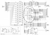
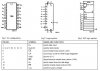
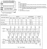
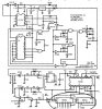
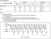
I am wiring 2 74HC166s that will convert a +5V DC signal from 16 push buttons into a serial signal, 2 74HC164s are 'supposed' to convert the serial signal and send a +5V DC signal to 16 LEDs.

I've found lots of schematics on the web for one chip, or the other, but none with the 2 chips used in tandem. I'd appreciate any help in connecting the controlling pins, the buttons and LEDs are a piece of cake, even I can figure that part out.

Any help is greatly appreciated.

Robert
:)
 
How do you want this to work? For example, set 16 input buttons, send the data, stop and read the LEDs, reset the leds and repeat.

The LEDs are going to be blinking while the data is being sent, so you have to stop to read them. You can send the data at high speed, using a clock under 25 mHz.

Tell us more about your intentions.
 
Ok,

my requirements:

- no LEDs light as long as no buttons pressed.
- when button pressed, corresponding LED lights, turns off when button released.


I'm including a schematic of a circuit with a pair of 74HCT166s as well as the pinouts and function.

Robert
:)
 

Attachments

  • 74hct166_sample.jpg
    74hct166_sample.jpg
    201.4 KB · Views: 414
  • 74hct166_pinout.jpg
    74hct166_pinout.jpg
    49.9 KB · Views: 431
  • 74hct166_function.jpg
    74hct166_function.jpg
    85.2 KB · Views: 418
And here is a schematic of a circuit with a pair of 74HCT164s as well as the pinouts and function. You can see that this circuit was not fed by 74HCT166s, so the wiring is different.

Robert
:)
 

Attachments

  • 74hct164_sample.jpg
    74hct164_sample.jpg
    100.6 KB · Views: 394
  • 74hct164_pinout.jpg
    74hct164_pinout.jpg
    41 KB · Views: 386
  • 74hct164_function.jpg
    74hct164_function.jpg
    52.2 KB · Views: 403
Or, you could say it that way... :D

Phase 2 of the project will be the addition of a PIC programmer written in BASIC between each halves of the circuit.

The 'plan' is the read the incoming signal, identify which button it came from by reading the data stream, and then control the LEDs by sending a 'modified' data stream. I'd like to override the LEDs, being able to light LED #6, when button #2 was pressed, stuff like that.

Phase 3 will consist of removing the LED part and linking this with a USB keyboard controller and generating pre-determined keystrokes within a game (controlled by the PIC chip). I've already mapped the matrix of a HP keyboard, so I know what pins on the 2 connectors I must complete in order to trigger any keystrokes.

I've tried to cut this into manageable parts, each concentrating on an important aspect of controlling a custom keyboard, that is the goal.

And then, I'm going to conquer the world!

:)
 
Status
Not open for further replies.

Latest threads

Back
Top