Electro Tech is an online community (with over 170,000 members) who enjoy talking about and building electronic circuits, projects and gadgets. To participate you need to register. Registration is free. Click here to register now.
Welcome to our site! Electro Tech is an online community (with over 170,000 members) who enjoy talking about and building electronic circuits, projects and gadgets. To participate you need to register. Registration is free. Click here to register now.
I would like to build a circuit that interfaces with my computers parallel port to detect if a led is on or off. Could I just replace the switch in the image with a photo diode? Thanks.
You don't need the 330Ω resistor in either circuit. Short it out.
Depending on the sensitivity required, you could attach a photo-transistor directly in place of the switch. Adding a 2nd transistor to boost the sensitivity is also possible as is adding a comparator circuit.
To use a photodiode you'd need to add a comparator IC for it to be able to drive the parallel port.
My circuit is based on the one from the website below. I basically just simplified the 5 input to a 1 input circuit. It refers to the 330 resistor as a "safety resistor". Are you sure I should leave it out? Parallel port output
The only problem with leaving it in is it adds a voltage drop. It is only really necessary on a pin which can be configured as either an output OR and input. You wouldn't need it on pins 10-13 & 15. That said, the safety resistor may save your ass (and pins 10-13 & 15) if you connected it to 12V or something.
I plan to mount the photo transistor right next to this led. Would I need to add a transistor to the circuit or is the light from the led bright enough for the photo transistor to detect?
It should be bright enough at close range. How far away is it going to be? Be sure to use a transistor with the same peak wavelength sensitivity as the LEDs peak wavelength output. What colour is the LED you have? The datasheet you posted covers 3 different colours and thus 3 different peak wavelengths.
I don't see many photo transistors @ Mouser which match that LED. What exactly are you trying to do?
There are photo interrupters which come as a package with matched emitters and detectors. These are used to detect objects passing through the slot.
Then there are opto-isolators for electrically isolating a signal, usually for safety reasons. They contain a optically linked LED and photo-detector in a single package.
How critical is it that the peak wavelength of the transistor match the wavelength of the led? If the wavelength of the led is different than the transistor, will the transistor detect the light? In my case ambient light is not a problem.
Material Wavelength range (nm)
Silicon 190–1100
Germanium 400–1700
Indium gallium arsenide 800–2600
Lead(II) sulfide <1000-3500
According to the datasheet this photo transistor is silicon. I do not how much difference there is between photo diodes and photo transistor with regard to wavelength range. EL-PT204-6C Everlight Photodetector Transistors
Yes, I did see that one. It doesn't look like it would be a standard photo-transistor, but rather a fiber optic transmitter going by similar part #s on **broken link removed**. Everlight's website doesn't list a datasheet for the PLT131, so I would avoid it.
How critical is it that the peak wavelength of the transistor match the wavelength of the led?
The sensitivity is a curve which looks like a steep mountain. So it's "off-colour" sensitivity could be anywhere from 50% to 5% of the peak sensitivity or less.
If the wavelength of the led is different than the transistor, will the transistor detect the light?
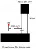
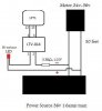
I have a motor that moves clockwise and counterclockwise. I would like to know when the motor is on or off. The direction of movement is not important. Visual indication and also feedback to the parallel port. See image.
Ah. I see now why you chose a bi-colour LED.
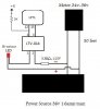
An AC opto coupler would be the solution for you. The AC opto couplers have two back to back LEDs just like your bi-colour LED does. The 859-LTV-814 from mouser should work in this application. You could connect it like this:
Ah. I see now why you chose a bi-colour LED.
An AC opto coupler would be the solution for you. The AC opto couplers have two back to back LEDs just like your bi-colour LED does. The 859-LTV-814 from mouser should work in this application. You could connect it like this:
Yes, it'll work perfectly. It will also work no matter which polarity is applied to the LED input. I chose it for this feature because of your reversing DC motor.
Sounds like you can get away without it. If the voltage between pins 12 & 25 is more than 2.4 V, then you can eliminate the +5v and 3k pullup resistor. You still need the 3.3K on the motor side to limit LED current.
Pin 12 goes low when the motor is on but it will randomly flucate between high and low. This problem seems to occur when the voltage on pins 1 and 2 is below 1.18v. Would I be correct in assuming that I need to use a resistor that has less resistance than the current 3.3K 1/2w in use.
motor off, pin 3 and pin 4 = 4.5v
motor on, pin 3 and pin 4 = 0.5v...0.08v
motor off, pin 1 and pin 2 = 0v
motor on, pin 1 and pin 2 = 1.06v...1.19v
What is the voltage across the motor at this point?
How is the motor controlled? ie: Is it controlled via a PWM motor speed controller or is it being fed straight DC?
You could reduce the resistor value to increase the LED current in the opto if the motor is running on straight DC. I wouldn't go beyond 30ma LED current as the max for the LTV-814 is 50ma.
This site uses cookies to help personalise content, tailor your experience and to keep you logged in if you register.
By continuing to use this site, you are consenting to our use of cookies.