Continue to Site

Welcome to our site!

Electro Tech is an online community (with over 170,000 members) who enjoy talking about and building electronic circuits, projects and gadgets. To participate you need to register. Registration is free. Click here to register now.

  • Welcome to our site! Electro Tech is an online community (with over 170,000 members) who enjoy talking about and building electronic circuits, projects and gadgets. To participate you need to register. Registration is free. Click here to register now.

OverVoltage Protection, is this design good enough ?

Status
Not open for further replies.

ItsMike

New Member
In one of my project I want to implement an Over Voltage + Over Current protection.
For Over Current I figured i'll just use a CB.

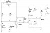
The Over Voltage I designed this way:

Source voltage goes into a voltage divider (2 resistors) and enters a comparator.
The second comparator input goes to a voltage reference (a zener diode).
The comparator output drives an npn transistor which drives the gate of a power mosfet.

The power mosfet is what switching the whole load which i want to protect to the ground or vcc (NMOS or PMOS).

I though of using a battery to power the comparator and zener, or perhaps use a 7805 to get 5v out of my power source. since the current used by the protection circuit is low I'd assume the 7805 won't need a heatsink.

How is the design ?
Is there a better way of doing it ?

Thanks in advance, Mike.
 
Seems like it should work. I think a voltage reference or a zener would be fine.
Post the circuit if you can.
 
It's more common to use a 'crowbar' circuit, as it's more or less 'fail safe' - doing it that way is 'fail dangerous'.
I'm not convinced there's that much difference between the two methods. In one case you open the circuit, in the other case you short the circuit to ground for over-voltage. In either case you are using a separate circuit to monitor for the over-voltage, and in either case if something fails in those circuits you may lose the protection.
 
I'm not convinced there's that much difference between the two methods. In one case you open the circuit, in the other case you short the circuit to ground for over-voltage. In either case you are using a separate circuit to monitor for the over-voltage, and in either case if something fails in those circuits you may lose the protection.

Semiconductor devices most commonly fail S/C - a crowbar thus fails in a completely safe mode, the other way fails and places high voltage on the supposedly protected circuit.
 
Than again if you use the crowbar scr method what happens of the over power supply over current protection fails ?
Either way it's not 100% safe.

For some reason I don't like the idea of short circuiting the power supply to blow the fuse or pop the CB.
 
Than again if you use the crowbar scr method what happens of the over power supply over current protection fails ?
Either way it's not 100% safe.

For some reason I don't like the idea of short circuiting the power supply to blow the fuse or pop the CB.

You might not like it, but it's the safest method, and is used commercially for that very reason.

Nothing is 100%, but a crowbar is a FAR hgher percentage than the other method.
 
My circuit will could use different kinds of power supplies and I'm afraid that one of the possibilities isn't over current protected.
I want to use a CB instead of a fuse so i guess it will take it ages to pop, this is why I don't really fancy the crowbar.

Anyways, i designed something like this:
I wonder if the FET's (Q2) placement is problematic at all, since it would have a low Vds(on) would it somehow drive the other fet (Q1) into active zone or something unpredictable ?

Should I also place a cap across R5 to stabilize the voltage a bit ?
 

Attachments

  • OVP-2.jpg
    OVP-2.jpg
    70.4 KB · Views: 203
My circuit will could use different kinds of power supplies and I'm afraid that one of the possibilities isn't over current protected.
I want to use a CB instead of a fuse so i guess it will take it ages to pop, this is why I don't really fancy the crowbar.

Crowbars are commonly used with CB's, one of the big advantages of crowbars is that it instantly protects the circuit as it shorts the incoming supply.
 
Crowbar circuit for over voltage & over current has been in use in TVs for years & work very well. In TV circuits they use an SCR to either blow a fuse or over load a SMPS to shut it down.
 
Status
Not open for further replies.

New Articles From Microcontroller Tips

Back
Top