Continue to Site

Welcome to our site!

Electro Tech is an online community (with over 170,000 members) who enjoy talking about and building electronic circuits, projects and gadgets. To participate you need to register. Registration is free. Click here to register now.

  • Welcome to our site! Electro Tech is an online community (with over 170,000 members) who enjoy talking about and building electronic circuits, projects and gadgets. To participate you need to register. Registration is free. Click here to register now.

Output two different voltages with comparator

Status
Not open for further replies.

savgrace

New Member
Hi everyone!
This is my first post here in quite some time. However, I have a quick question that I'm sure someone with a bit of savvy could answer easily :p.

How do I output two different voltages with a comparator? For example, if I had an input that varied between 0 and 1 V and wanted an adjustable reference but I wanted to output 0.2(Low) or 0.8(high) Volts?

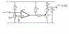
I was thinking of using two comparators both using the same input but each ones output was tied to a different voltage divider. The only problem with this is it would create conflicting signals on the output, or in other words, one would have to be off while the other is on... Does someone have a better suggestion?

Thanks A LOT in advance! :D (By the way, I'd be using this to bias the oxygen sensor output on a car)
 
Last edited:
In instrumentation, such device is called Trip Amplifier, for the same input signal, two reference are used and two output are taking from two different relays, on as Normally open and the other Normally closed. The two output are connected in series to the load to be controlled.

The idea for two output from one input is to set your comparator to act at RASE or FALL of the signal. BTW this is solved by the PIC comparator.
 
Thanks for the reply aljamri. Relays wouldn't work because of the speed of the switching (several Hz). I'm not sure what you meant by
set your comparator to act at RASE or FALL of the signal
:p I also looked at the PIC datasheet and didn't see anything about dual output voltages or anything... Could you clarify a bit more man? :D Thanks!
 
take for example PIC 12f675, on page 35, talking about bit 4 CINV.
 

Attachments

  • 123.GIF
    123.GIF
    24.7 KB · Views: 163
I'm thinking I don't understand your question.

You want one output at .2 volts and .8 volts at the same time?
 
What I understood is that he wants his a device to work ON and OFF within certain range, like to start when the signal is 0.2v and stops when the same signal reaches 0.8v. So I suggested to use two different comparators for each point, and ANDed them either with relays ( he dose not accept it ) or he can do this using the proper PIC routine to AND the output of two comparators.
 
Last edited:
Nope. Here, let me see if I can give a better description.

Let's say I'm using a single comparator. My Reference Input on -(inverting) is between 0-1V (using a Potentiometer) and my Input is on the + (non-inverting). This input will also range between 0-1V. However, usually the Comparator will output a High which on the LM339 is about equal 3.5V (with 5V Vss) and 0V when it is low.

I want the Comparator to OUTPUT 0.2V when it is low and I want it to output 0.8V when it is high. I could get the 0.8V on High relatively easily using a voltage divider and dividing up the 3.5V but how do I get 0.2V when it is low? Could I somehow tie the comparators ground to a 0.2V reference or something?


Hope that makes more sense?:p
 

Attachments

  • comparatorExample.jpg
    comparatorExample.jpg
    25.9 KB · Views: 146
Last edited:
Divider

The comparator is open collector so a divider should work.
Actually you can leave out the 150 ohm. The saturation voltage on the 339 is .250 typ.
 

Attachments

  • divider.PNG
    divider.PNG
    55.2 KB · Views: 154
Last edited:
Solution :)

Thanks everyone for your help. I did come up with a solution through trial and error. It works (at least on the breadboard it does) right now. Anyone see any improvements that could be made for reliability/stability?

I attached a schematic of what I built and the description is pretty self explanatory. For anyone wanting help with something similar here is what I got. This could potentially be used as a better EFIE type of device for any HHO fans out there. :p
 

Attachments

  • comparatorExample.jpg
    comparatorExample.jpg
    42.8 KB · Views: 145
Status
Not open for further replies.

Latest threads

New Articles From Microcontroller Tips

Back
Top