Electro Tech is an online community (with over 170,000 members) who enjoy talking about and building electronic circuits, projects and gadgets. To participate you need to register. Registration is free. Click here to register now.
Welcome to our site! Electro Tech is an online community (with over 170,000 members) who enjoy talking about and building electronic circuits, projects and gadgets. To participate you need to register. Registration is free. Click here to register now.
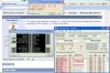
Trying to simulate NG Analogue Tutorial eleven, loaded 11.3, (tested it in reality and worked fine), I tried to connect the LCD and changed the analog input but LCD seems not working, and error message appears as in the attached shot.
Sorry Ian, Sorry Eric, I was busy trying to get it work, so I've not noticed your posts.
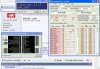
Finally with your help I've got it working. Only I could not change the reference voltage as per NG analogue board so instead of 2v input I'm getting 4v on LCD.
Yes, in "Reading 4 - 20 mA on LCD using PIC16F876A", Eric told in post #7 that I can remove the bottom end +1V offset in the program, to get a Span of 4V.
I postpone asking him HOW, for future. Is that sort of what you Ian talking about ?
hi aljamri
If you are using the full 10 bits of the adc, ie 1023decimal and the Vadc max is 5V
To subtract the 1Vdc offset you need to subtract [1/5] *1023 = 205 from the reading.
This will give a value of 0 thru 818 for 0V to 4V
If you set the resistor driving the adc input for a maximum of 4.89V
you will get [4.89/5]*1023 = ~1000 counts, then subtract 200 to leave 800 counts which represents 4V input.
As I'm not aware about JAVA application and the site owner was giving early warning that he well not accept any questions in this regards, I prefer OshonSoft and if Protuse not of huge size, it would be my first choice.
Anyway, I've got a fresh question about OshonSoft and I do not know, shall I start a new thread or continue in this. I'll start here and waiting for any advise to make a new one.
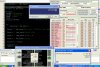
My Question is regarding a suggested ADC routine by be80b2 in " https://www.electro-tech-online.com/threads/reading-4-20-ma-on-lcd-using-pic16f876a.119563/ " post #17. When I made the circuit, the LCD shows only square, so I thought of my hardware problem, so that I decided to simulate it with OshonSoft and see what is the result. It seems the routine is updating LCD port PORTB one time, and then it goes for endless loop without updating it any more. The attached picture shows the result
This site uses cookies to help personalise content, tailor your experience and to keep you logged in if you register.
By continuing to use this site, you are consenting to our use of cookies.

") thank you Ian
thank you Ian