Continue to Site

Welcome to our site!

Electro Tech is an online community (with over 170,000 members) who enjoy talking about and building electronic circuits, projects and gadgets. To participate you need to register. Registration is free. Click here to register now.

  • Welcome to our site! Electro Tech is an online community (with over 170,000 members) who enjoy talking about and building electronic circuits, projects and gadgets. To participate you need to register. Registration is free. Click here to register now.

Oscilloscope repair

Status
Not open for further replies.

zachtheterrible

Active Member
I just got a good bargain on an oscilloscope off ebay- a 250MHZ Tektronix 475A dual trace for $70 :lol: The way I see it, I can sell my other 20MHZ scope that I got for $80 and cover my costs :wink:

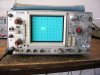
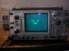
There is one problem with the scope though that can probably solved easily. If not I'll just resell it. The beam is stretched out, I don't know any other way to explain it. In one picture, the beam is not moving at all, so it should be a dot, not a line like you see. In the the other picture you can see the distortion of the waveform caused by the beam being stretched out.

So how do I fix this?
 

Attachments

  • dscn0199.jpg
    dscn0199.jpg
    178.4 KB · Views: 2,868
  • dscn0200.jpg
    dscn0200.jpg
    173.1 KB · Views: 2,566
Thanks, I'll look at that. Just have to figure out how to get the stupid thing apart first :lol:
 
Zach,
I concur with Ruslk re the first photo.

In the second photo, it looks to me as though either the Horzontal amp is lacking in gain or the Delayed Sweep is faulty. Does the X shift move the trace?

Was the delayed sweep on when you took the photo?

If so, does the Delayed Sweep delay control move the trace?
 
ljcox said:
Zach,
I concur with Ruslk re the first photo.

In the second photo, it looks to me as though either the Horzontal amp is lacking in gain or the Delayed Sweep is faulty. Does the X shift move the trace?

Was the delayed sweep on when you took the photo?

If so, does the Delayed Sweep delay control move the trace?
Len, if you look at the sweep control knob, he has it in X-Y mode. I think this is intentional, as he should get a dot on the screen with no inputs, as he says.
 
Ron,
I was using a friend's computer and had limited time. If both photos are supposed to show only a dot, then there must be ripple in the Y amp and ripple or noise in the X.

Zach,
Do you have a Service Manual? Or a circuit diagram?

If not, there is still much you can do.

1. do a visual examination looking for electrical, mechanical or chemical damage, eg. there may be hairline cracks in the PCB, broken components, overheated components or corrosion (partic if it has lived near the sea) etc.

2. check all of the electrolytic capacitors, they tend to fail after a few years. If you can (ie. have the equipment) measure their capacitance, leakage resistance and ESR. Low cap or high ESR can cause ripple in the supply lines. If not then replace the electros that are used for power supply filtering.

3. Measure the supply rail voltages. Also examine the supply rails with your other scope using AC coupling and see how much ripple (60 Hz or 120Hz) there is. If you don't have a circuit, you will have to guess. Steer clear of the high voltage section. Your problem(s) don't appear to be HV related anyway.

4. note the effect of all of the controls, eg. does the Y shift actually make it move vertically? Is there any limit to the movement, eg. will move to the top of the screen but not to the bottom.

The X amp in my HP scope failed recently (the latest in a long line of faults) and so the trace was only visible at the left side and could not be moved very far to the right with the X shift. A resistor had gone high and 3 others were trying to go high.
 
Ron is right, I had it in x-y mode and I should be getting a dot, not a line.
Here's what I found when I took the thing apart-

1. I hooked up my scope to the + side of about 6 electrolytic supply caps, which I'm guessing is the supply rails as well. I found a triangle wave in the neighborhood of about 1 volt riding on the supply rails. The frequency was 125hz- because of the bridge rectifiers correct?

2. I measured the ESR of the capacitors with a ohmeter and they had resistances ranging from 10k-70k. Of course they were in the circuit and i have a sneaking suspicion i might be reading the bleeder resistors because the capacitors wouldn't keep their charge after i turned it off.

3. I found an index card that said that the ch. 2 x10 attenuator was repaired in '56! I think I should probably replace those electrolytics.
 
zachtheterrible said:
Ron is right, I had it in x-y mode and I should be getting a dot, not a line.
Here's what I found when I took the thing apart-

1. I hooked up my scope to the + side of about 6 electrolytic supply caps, which I'm guessing is the supply rails as well.
I found a triangle wave in the neighborhood of about 1 volt riding on the supply rails.
The frequency was 125hz- because of the bridge rectifiers correct?
Yes, It is double the line frequency and you have 60 Hz over there.

2. I measured the ESR of the capacitors with a ohmeter and they had resistances ranging from 10k-70k.
Of course they were in the circuit and i have a sneaking suspicion i might be reading the bleeder resistors because the capacitors wouldn't keep their charge after i turned it off.

You should measure them with the power off.
10k - 70 k is rather high. So if correct, then they need changing. Normally the ESR is < 5 Ohm and when high only a few Ohm above the nornal.
The normal ESR varies from one cap to another depending on their capacitance and voltage rating.
Do you have a list of ESR versus C and V? So your readings may be wrong.
I suggest you remove one and measure its ESR when out of circuit.

3. I found an index card that said that the ch. 2 x10 attenuator was repaired in '56!
I think I should probably replace those electrolytics.
I doubt if it was 1956, but yes, take them out one by one and check them.
If you confirm that your ESR readings taken while in circuit agree approximately with those taken when out of circuit, then replace all.
How does the scope perform when it is not in the X-Y mode?
 
Undressing a Tek 475A

To get the 475A out of the case, put the front cover on the scope, flip the tilt-handle out of the way of the front panel and stand the scope on its face. If you don't have the front cover, leave the scope on its feet and work from there, although the process will be a heck of a lot more difficult because of the effects of gravity.

Remove the four feet on the rear using a #2 Pozidriv (or less effective, a #2 Phillips) screwdriver. Remove the two other screws top and bottom center. Remove the plastic ring that holds the cover on. Lift the cover by the tilt handle axles straight up and off the scope.

Installation is the reverse of removal. But when you get the cover down into place, you'll have to tap the top and bottom edges with your fingers to get it to slip into the groove on the front casting.

Yes, 1956 for a repair is impossible. The 475 came out around 1974 and the 475A around 1980 or so. The 475 and 475A are nearly identical -- the extra bandwidth comes primarily from tweaking up the output amplifier. So if you need a "hangar queen" for parts, a 475 should work about as well and be more readily available as more of them were made.

I'd suggest getting your test scope probe into the horizontal amplifier with the 475A in the X-Y mode and take a peek along the signal path and see where this spurious signal starts and stops to isolate the defective stage. It may be nothing more than the replacement of a decoupling cap in one of the supplies.

Troubleshooting help for the scope can be found on the Yahoo! Tekscope forum at https://groups.yahoo.com/group/TekScopes It's a good spot for both troubleshooting help and parts.

Dean
 
Does anyone know of a similar site for HP scopes?

I have a 1740A and may, one day need spare parts.
 
I think you can send it in for repair but I don't know what it will cost.
I had a broken one and ended up throwing it out because there was noone to fix it locally,but you can mail it out to be fixed.
 
I'm sorry, when I said ESR, I didn't mean ESR. I just measured the cap with a ohmeter to see if it was shorted. How do you measure ESR?

The scope works fine when it's not in x-y mode. It's like looking at a waveform made with a caligraphy pen held horizontal. I hope it's just one of the supply caps because I really have no idea what I'm looking at, there are a lot of boards on the scope. I'd have to get a repair manual.

I wonder why I found that index card taped in there with those words on it :?
 
zachtheterrible said:
I'm sorry, when I said ESR, I didn't mean ESR. I just measured the cap with a ohmeter to see if it was shorted. How do you measure ESR?

With an ESR meter! - and I'm not taking the pi**!.

An ESR meter measures the impedance (NOT the resistance) of the capacitor at 100KHz.
 
Do a search for "esr meter". You'll get several hits that show you how to do it without buying another meter.
 
ESR = Equivalent Series Resistance.

My understanding is that it is resistance of the connections to the plates which can change with age due to (I assume) the aging of the electrolyte.

Here is a chart of the maximum ESR for normal caps (taken from my ESR Meter that I built as a kit)
 

Attachments

  • esr_table.gif
    esr_table.gif
    8.1 KB · Views: 1,632
The 475A is old enough that Tek may have considered it obsolete. Repair by them won't happen and new parts will be dicey. The scope DOES NOT work fine when not in the XY mode. The waveform that you displayed in your original post is the result of the problem that's messing up the beam in the X-Y mode. Since the vertical amplifier feeds the horizontal amp in the X-Y mode, you can rule that out as the culprit. The problem has to be in the horizontal amp.

I've never seen a similar Hewlett-Packard-oriented site like the Yahoo! Tek site. The Yahoo! site is an independent third-party site that is not connected to Tek in any way. Since Hewlett-Packard, now Agilent, manufactured such a broad line of electronic, computer and medical equipment, a site revolving around it would have to have lots and lots of different categories just to make it somewhat navigatable. As far as scopes go, I've really never known an hp scope that was worth repairing other than the 130C and maybe the 140-series mainframes and their plug-ins. The 180-series and most of the portable scopes had knobs that were such nuckle-busters that I hated using them.

Dean
 
The scope DOES NOT work fine when not in the XY mode. The waveform that you displayed in your original post is the result of the problem that's messing up the beam in the X-Y mode. Since the vertical amplifier feeds the horizontal amp in the X-Y mode, you can rule that out as the culprit. The problem has to be in the horizontal amp.

I'm quite aware that it doesn't work fine when in XY mode. If the problem is not the supply filtering caps, I'm just 'gonna resell it on ebay, not worth the time and frustration, and lack of parts :lol:
 
I would agree ( as stated above ) that it is likely the supply and/or bypass caps. The scope is old enough that they are due for replacement anyways. Whenever this scope is listed at one of the refurb/recal places, they always state that these caps have been replaced. It is a nice enough scope to warrant a few hours and a few dollars worth of caps.

Replacing supply caps and fixing cold solder joints has kept food on the table for service techs for years. :D
 
The 475A was Tek's top-of-the-line portable analog scope, second only to the 485 (which had never been exceeded in performance) and is worthy of repair, especially for this problem. Don't expect to troubleshoot any Tek product without a service manual or you might as well just take a hammer to the thing, for it will do just as well. I'm assuming that you don't have a manual since you didn't know how to remove the case.

I'm certain that this is probably a simple fix and you're going to have to run the signal path of the horizontal amp to find it. This was originally a $3500 scope and since the jug is good, it's worth the repair. It appears to be in good mechanical condition.

Dean
 
Mr. Huster is right, you will need the manual to do a proper job. It is available on the internet, complete service, operators, manitenance and calibration, including schematics, part diagrams and waveforms.

The military's version is here in the boat anchor archives:

https://bama.edebris.com/manuals/tek/475/

hope you get it fixed!
 
Status
Not open for further replies.

New Articles From Microcontroller Tips

Back
Top