Continue to Site

Welcome to our site!

Electro Tech is an online community (with over 170,000 members) who enjoy talking about and building electronic circuits, projects and gadgets. To participate you need to register. Registration is free. Click here to register now.

  • Welcome to our site! Electro Tech is an online community (with over 170,000 members) who enjoy talking about and building electronic circuits, projects and gadgets. To participate you need to register. Registration is free. Click here to register now.

oscillator

Status
Not open for further replies.
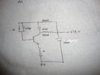
I am a undergrad student.I have a problem with a oscillator circuit.I have found a oscillator circuit from net and using it as a oscillator in my circuit.But my problem is that i could not find that what type of oscillator it is and what is it's operation?It would be helpful for me if someone please help me to know the type and operation of the oscillator .Thank you.I have given the figure attached.
 

Attachments

  • edited.jpg
    edited.jpg
    3.5 MB · Views: 240
Not a particularly good one. Here is a sim of it. Note that V(c) and V(a) have approximately equal amplitudes, but they are 180 degrees apart. This shows that the network consisting of L1, L2 and C1 is a Pi-section high-pass filter which has a gain of ~1 and a phase shift of 180 degrees at the frequency of oscillation.
If the transistor has a gain of slightly greater than -1, then the circuit will oscillate, which it does. Note the un-bypassed emitter resistor, which is why the transistor gain does in fact have a low gain. Also note the low amplitute, and the harmonic distortion.

I have never seen this circuit before, but I would call it a variant of the Colpitts Oscillator.
 

Attachments

  • osc1.jpg
    osc1.jpg
    237.5 KB · Views: 213
I played with the bias, and came up with this: Higher amplitude and lower harmonic distortion.
 

Attachments

  • Osc1m.jpg
    Osc1m.jpg
    234.6 KB · Views: 223
Not a particularly good one. Here is a sim of it. Note that V(c) and V(a) have approximately equal amplitudes, but they are 180 degrees apart. This shows that the network consisting of L1, L2 and C1 is a Pi-section high-pass filter which has a gain of ~1 and a phase shift of 180 degrees at the frequency of oscillation.
If the transistor has a gain of slightly greater than -1, then the circuit will oscillate, which it does. Note the un-bypassed emitter resistor, which is why the transistor gain does in fact have a low gain. Also note the low amplitute, and the harmonic distortion.

I have never seen this circuit before, but I would call it a variant of the Colpitts Oscillator.
I am actually confused about what type of oscillator it is about about how it is operating ?can you please tell me how it is operating ?
 
If you do not know how oscillators work, Google Barkhausen Criterion and the Colpitts Oscillator. Read the Wikipedia entries on both those topics.
 
MikeML said:
I have never seen this circuit before, but I would call it a variant of the Colpitts Oscillator.
I agree that it is a strange circuit which I dont think that I have seen before.
However, because it is using a tapped* inductor, it looks to me to be more of a variation of the Hartley oscillator.

*But then can the inductor be said to be tapped when there is no obvious mutual inductance between the two coils?
However at resonance, it should give the required 180deg phase shift for oscillation (The transistor providing the other 180deg).

JimB
 
...
However, because it is using a tapped* inductor, it looks to me to be more of a variation of the Hartley oscillator.

*But then can the inductor be said to be tapped when there is no obvious mutual inductance between the two coils?
However at resonance, it should give the required 180deg phase shift for oscillation (The transistor providing the other 180deg).
Thats why it is more akin to Colpitts; the primary difference is that a Colpitts usually uses a low-pass Pi section, this one a high-pass Pi.
 
Thats why it is more akin to Colpitts; the primary difference is that a Colpitts usually uses a low-pass Pi section, this one a high-pass Pi.
You have me confused there Mike.
I must admit that I had never considered the low-pass vs high-pass aspect of the circuits before, and I agree that this is high-pass.

However, cribbing from Wikipedia, we have:
The distinguishing feature of the Hartley oscillator is that the tuned circuit consists of a single capacitor in parallel with two inductors in series (or a single tapped inductor), and the feedback signal needed for oscillation is taken from the center connection of the two inductors.
and
The distinguishing feature of the Colpitts oscillator is that the feedback for the active device is taken from a voltage divider made of two capacitors in series across the inductor.
Which leads me to think that the circuit in question does not really fulfill the description of either the Colpitts or the Hartley.

All this gets us nowhere towards helping the OP to put a name to this circuit.
Maybe we should just call it Clint Eastwood...
...The Oscillator with No Name. ;)

JimB
 
Last edited by a moderator:
All the Hartley oscillators I have seen or played with use the mutually-coupled inductors as an auto-transformer to achieve a voltage step-up, where one end of the windings is common.

The amplifier is usually an emitter-follower or source-follower with a voltage gain of less than one, so to make it oscillate, the loop gain requires the voltage step-up in the transformer.

Also, the transformer network at resonance has zero phase shift, so the amplifier needs a non-inverting gain.

Here is the simplest Hartley I know:

Hartley.jpg
 
Last edited:
I know sometimes teacher want to match a name to the circuit originator. Better to understand how the loop phase shift and gain gets from input to output. In this case the two 922 nH's and 4.7 nF form the primary resonate tank with approximately 180 degree phase difference across the 4.7 nF. Each side is not loaded exactly the same as side going to base of transistor is loaded with a lower impedance then collector output and this causes some minor deviation from the 180 deg shift at oscillation. There is also not exactly 180 deg shift from base to collector of transistor.

A lot of folks got their names famous simply by grounding the same basic oscillator at different points in the circuit.
So sir what do you suggest that what type of oscillator it is?As I am not expert I am not understanding the operation?
 
There are two basic ways to accomplish the feedback phase shift. One uses a split capacitor which is in the Colpitt class. The other is using a tapped inductor which is in the Hartley class.

This particular uses the two inductor as a center tapped coil (presumably without mutual coupling between coils). Loosely I would put it in the Hartley class.
So what is the operation of this oscillator?I am not understanding how it is operating?But it is giving good and stable frequency.
 
I am feeling rakibulraju became more confuse than before due to such discussion!
 
So what is the operation of this oscillator?

Using an edited version of one of Mikes simulations:
Oscillator.JPG

Resistors R1 and R2 set the DC operating conditions for the transistor.
The Collector of the transistor gets its DC supply via the inductor L2.


Editing here:
(for the second time, because the first edit just dissapeared into the bit bucket!)
L2 provides a collector load which is very low resistance at DC and equal to the reactance of L2 at the operating frequency.
This statement is over simplified and is just plain wrong. What I should have said is:
The collector load for Q1 is provided by the overall impedance of L2 in parallel with the series imedance of L1 and C1.
The resulting impedance will be a maximum at the resonant frequency of the tuned circuit, and lower at all other frequencies above and below the resonant frequency.
This gives the amplifier maximum gain at the resonant frequency of the tuned circuit.
End of edit.

Capacitor C2 decouples the DC supply so that no AC can exist on the supply line.

The transistor is in a common emitter configuration, and so a signal at the base will be inverted at the collector (ie for a sine wave it will be phase shifted by 180 degrees).

The tuned circuit comprising L1, L2 and C1, at its resonant frequency the voltage at point "c" will be phase shifted by 180 degrees compared to point "a". This can be clearly seen from Mikes simulation plots.

The DC supply to the base of the transistor is via L1 and R1.
When the circuit is oscillating there will be an AC signal superimposed on the DC supply to the base.
That signal to the base will be 180 degrees phase shifted ffrom the signal at the collector.

So, we have 180 deg phase shift in the transistor, 180 deg phase shift in the tuned circuit, so the feedback signal is in phase with the original signal at the base, and provide that the gain around the circuit is greater than 1 at the resonant frequency of the tuned circuit, we will have a sustained oscillation.

I think that just about does it.

JimB

Edited at 11:30 26/12/13
 
Last edited:
I am feeling rakibulraju became more confuse than before due to such discussion!
OK, I have given a basis analysis of the circuit, please feel free to expand on it.

JimB
 
...
So, we have 180 deg phase shift in the transistor, 180 deg phase shift in the tuned circuit, so the feedback signal is in phase with the original signal at the base, and provide that the gain around the circuit is greater than 1 at the resonant frequency of the tuned circuit, we will have a sustained oscillation.

And that is why it is more like a Colpitts than a Hartley..., although, I guess you could ground the center-tap on a Hartley, and then the amplifier would have to have 180deg of additional phase shift...
 
Last edited:
It's more Hartley than Colpitts. In fact it's a series-fed Hartley because of the DC current flow, as that is the distinguishing characteristic between the two "Hartley's".

From wiki ..
The distinguishing feature of the Hartley oscillator is that the tuned circuit consists of a single capacitor in parallel with two inductors in series (or a single tapped inductor), and the feedback signal needed for oscillation is taken from the center connection of the two inductors.

Wiki doesn't mention the series-fed and shunt-fed Hartley Oscillators, however, they both are discussed in the NEETS Module 9 Introduction to Wave Generation and Wave Shaping
The HARTLEY OSCILLATOR is an improvement over the Armstrong oscillator. Although its frequency stability is not the best possible of all the oscillators, the Hartley oscillator can generate a wide range of frequencies and is very easy to tune. The Hartley will operate class C with self-bias for ordinary operation. It will operate class A when the output waveform must be of a constant voltage level or of a linear waveshape. The two versions of this oscillator are the series-fed and the shunt-fed. The main difference between the Armstrong and the Hartley oscillators lies in the design of the feedback (tickler) coil. A separate coil is not used. Instead, in the Hartley oscillator, the coil in the tank circuit is a split inductor. Current flow through one section induces a voltage in the other section to develop a feedback signal.
The NEETS modules are easily found on the internet ... or you can use **broken link removed**

Also from wiki
The distinguishing feature of the Colpitts oscillator is that the feedback for the active device is taken from a voltage divider made of two capacitors in series across the inductor.

The distinguishing feature of the Hartley oscillator is that the tuned circuit consists of a single capacitor in parallel with two inductors in series (or a single tapped inductor), and the feedback signal needed for oscillation is taken from the center connection of the two inductors.

The Armstrong oscillator is sometimes called a tickler oscillator because its distinguishing feature is that the feedback signal needed to produce oscillations is magnetically coupled into the tank inductor in the input circuit by a "tickler coil"

The Clapp oscillator is a Colpitts oscillator that has an additional capacitor placed in series with the inductor.
 
Sorry for the highjack, but Mike would you mind posting the sim please? I am trying to learn LT spice, and I would like to play with the sim a bit. I tried to copy it but didn't get it to work, so wondered if you would post it so i can look at how you did it.
Thank you
LG
 
Status
Not open for further replies.

Latest threads

New Articles From Microcontroller Tips

Back
Top