Maverickmax
New Member
Hi
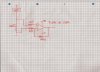
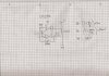
I have noticed that there is a latch up on the opamp chip everytime I power it up. For example, I have tried to use TL8048N and OP07 which automatically latch up to postive rail. I have been told that the voltage is out of the range especially in input common mode voltage. So I went to look at their datasheet and found out that TL084's input common mode voltage within +/- 15V and OP07 only accept the voltage within =/-14V.
At the moment, I use a single power rail instead of dual. Someone said that the op-amp such as TL084 could not detect the voltage within 3V and I could not find that information in the TL084.
By the way, I am using the op-amp for current sensing which will later connected to ADC. Again I do not understand when I have been told that op=amp must have input common mode votlage to 0V and Positive supply. What this does mean?
Please help me to identity this issue?
MM
Last edited:
")