Electro Tech is an online community (with over 170,000 members) who enjoy talking about and building electronic circuits, projects and gadgets. To participate you need to register. Registration is free. Click here to register now.
Welcome to our site! Electro Tech is an online community (with over 170,000 members) who enjoy talking about and building electronic circuits, projects and gadgets. To participate you need to register. Registration is free. Click here to register now.
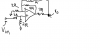
Lets do this a little at a time. The input impedance is 4R. The (+)input of the amp is mega ohms and does not count hare. If you measure from Vin to ground you will see 2R +2R=4R. Simple.
Lets look at the gain of the amp one little piece at a time.
The two input resistors make a 2:1 voltage divider. So the (+) input sees 1/2 of Vin.
The gain for this section is 0.5x. Simple.
The gain of the amp is 1+(R(-)input to output/R to ground).
R to ground is 2R.
The resistance from (-)input to output is a little complicated.
>There is two parts:
>>4R is simple.
>>There is 1R + 3R =4R
So the feedback resistance is 4R//4R. 4R parallel with 4R = 2R
So the gain is 1+(2R/2R) =2
The gain from input to output of the amp is: (note not the "output" but the output of the amp, there is a difference)
The resistors on the (-) pin cause a gain of 2.
The resistors on the (+) pin causes a gain of 0.5
So these two gains multiply to get 1.
Recap:
Pretend Vin is 1 volt.
After the two input resistors there will be 0.5V on the (+) input.
(remember the amp will try to get the same voltage on both inputs.)
The output of the amp will go up trying to get both inputs at the same 0.5V.
There is a 2R from (-) to ground.
There is 2R from (-) to output of amp. 2R=4R//(R1+3R)
The amp output is at 1V.
1V in and 1V out so the gain of the amplifier is 1x.
Not done yet!!!!!!
The output you are asked to think abut is not the output of the amp but has a voltage divider in it. 1R and 3R.
So if you have a divider made up of 3R and 1R the output will be 1/4.
BUT your divider is not that simple. On the 3R end there is a 1V signal. On the 1R end there is a 0.5V signal.
You output is something between 1V and 0.5V, but closer to 0.5.
So I did not quite give you the answer but almost.
Have you learned how to do network analysis using Kirchoff's KVL and KCL laws, such as nodal, mesh and loop analysis? What efforts have you made so far to solve the problem?
Assume R=1k, Vin=1 Volt, by following Ron's method, I can find the circuit's output voltage Vo, but what is the definittion of the output current? Is the output current the one indicated in the following circuit? Do we need to consider if there is a load connected to the circuit's output terminal?
Assume R=1k, Vin=1 Volt, by following Ron's method, I can find the circuit's output voltage Vo, but what is the definittion of the output current? Is the output current the one indicated in the following circuit? Do we need to consider if there is a load connected to the circuit's output terminal?
The output current depends on the load attached to Vo. However, the output impedance is independent of the output current load, and is determined by the circuit configuration and values. Hint: The output impedance is equal to the value of the output voltage with no load, divided by the short circuit current when Vo is connected to ground.
The output current depends on the load attached to Vo. However, the output impedance is independent of the output current load, and is determined by the circuit configuration and values. Hint: The output impedance is equal to the value of the output voltage with no load, divided by the short circuit current when Vo is connected to ground.
My thoughts are on the idea there is no load. Because a load to ground will alter the feedback.
This is a jack ass of a circuit. It is for students to think and not a real life example.
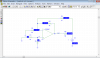
Using the PSpice circuit form #10: The output is at the junction of R4 and R6.
Output impedance can be found by jerking on the "output" and seeing how stiff it is.
The output of the op-amp is very stiff! So one thought is that the output impedance is some what, the 3k from "output" to the op-amp.
BUT!!!
If you were to lift the output by 1V that would cause current to flow through R4 into the (-) input. That will cause the op-amp to pull its output down and fight the effect.
Heidi, Please put a 1V "battery" from the output to ground and see how much current it takes to pull the output to 1V. (change the input to 0V, V1=0)I think it will take 2.66mA or about 600 ohms. (using Ron's spice in side my head) lol
The voltage at node p is Vp=0.5V, so is the voltage at node n, Vp=Vn=0.5V.
The current through R3 (let's call it I3) flowing to the left is I3=0.5/2k=0.25mA.
The current through R4 to the right is I4=0.5/1k=0.5mA.
These two currents must come from the current through R5, that is from node out to node n, hence there's a voltage drop of 0.75m*4k=3V, so Vout=0.5+3=3.5V.
The short circuit current Is=Vout/R6 + Vn/R4 =3.5/4k + 0.5/1k =1.667mA.
The open circuit voltage V0 can be found to be Vo=0.625V by Ron's method, so the output resistance is equal to Vo/Is=0.625/1.667m=375Ω.
Heidi, Please put a 1V "battery" from the output to ground and see how much current it takes to pull the output to 1V. (change the input to 0V, V1=0)I think it will take 2.66mA or about 600 ohms. (using Ron's spice in side my head) lol
Thank you for mentioning another way of finding the output impedance. I'm glad it has the same result: 1/2.667m=375Ω.
But I'm more concerned about why we define an output impedance like that. There must be some purposes.
I mean, what can it tell us if we know a circuit's output impedance?
For example, if we know a circuit's output voltage with no load Vo, and the circuit's output resiatance Ro. Then for any load Rl connected to the output terminal, we can easily find the voltage across the load by voltage divider rule.
But in the opamp example, which node voltage plays the role of Vo in the above diagram?
Although I'm more curious about what it can tell us when we know a circuit's output impedance, I have to get some sleep now, it is almost 2:30 am in Taipei. Sorry!
This site uses cookies to help personalise content, tailor your experience and to keep you logged in if you register.
By continuing to use this site, you are consenting to our use of cookies.

")
 Sorry!