Continue to Site

Welcome to our site!

Electro Tech is an online community (with over 170,000 members) who enjoy talking about and building electronic circuits, projects and gadgets. To participate you need to register. Registration is free. Click here to register now.

  • Welcome to our site! Electro Tech is an online community (with over 170,000 members) who enjoy talking about and building electronic circuits, projects and gadgets. To participate you need to register. Registration is free. Click here to register now.

opamp output not 'calibrated'

Status
Not open for further replies.

pomme

New Member
Hi all,

I'm not too sure if I can explain the problem I am having clearly, but i'll give it a go.

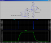
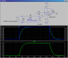
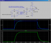
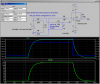
In the schematic attached, I am using the voltage across resistor Rsense (0.1 Ohm) as an input to a PLC. Because the maximum current flowing through is 2A, even the maximum voltage drop across Rsense (0.2V) will not be enough to trigger the PLC input. As such, I have passed it through a non-inverting amplifier with a gain of 81.

When testing the circuit, I found that the output voltage of the opamp (LF412CN) is actually about 120 bigger than the input. This is the case even at smaller currents. I do not know what is causing this problem. I have a feeling it might be the capacitance or inductance in the circuit, but right now, I don't know how to fix it. Any help from you guys would be greatly appreciated.

Thanks.
 

Attachments

  • Schematic Prints 3.pdf
    9.5 KB · Views: 259
Last edited:
There is no problem. How did you calculate a gain of 81? The gain of your non-inverting circuit is 1+Rf/Rn = 121 which about what you measured.

(Note: Ri is in parallel with Rsense and thus has no significant effect on circuit operation. It can be removed)
 
Hi there,


Actually there could be a problem here if you are using the LF412. You should probably be using the LF412A as that has a better common mode voltage range. The LF412 may act strange if you try to run an input near ground, while the 'A' package should have no problem with this, although the data sheet isnt 100 percent clear on this either.
Of course you should check to make sure that your 1.5k resistor is really 1.5k and not really 1k as that would do it too.

Carl:
I made the same mistake, it's a 1.5K input resistor not a 1K resistor so the gain is really 81 :)
I needed to zoom in on the schematic a little to see it properly.
 
Last edited:
crutschow, thanks for your reply. I found the gain by: (120k/1.5k) + 1 = 80 + 1 = 81. I thought of removing Ri, but in some readings I have done, they mention to keep it for some coupling reasons - not too clear to me.
 
What voltages are on Vcc and Vee, respectively?
 
MrAl, thanks for your reply. When u say 'run an input near ground' do u mean the input to the non-inverting terminal is too small? I have not thought about that, but would this really be an issue? I have tried different gains, and the measured values are very far off.
 
Vcc = 16.7V and Vee = -17V. There is no particular reason for the difference in magnitude. I have set them both to 17V, it's just the power supply being a bit inaccurate. Ideally Vcc and Vee are +/- 17V respectively.
 
Yes, I somehow misread the resistor value. But perhaps the resistor is actually 1k which would explain the gain of 120.

Edit: How do you measure the gain?

Ri would balance the output offset voltage effect of the input offset current if you had a high impedance source, but with a source of 0.1 ohms, Ri has no effect.
 
Last edited:
I have measured the 1k5 resistor several times to make sure I am using the right one, and it is (about 1.48k)
 
MrAl, thanks for your reply. When u say 'run an input near ground' do u mean the input to the non-inverting terminal is too small? I have not thought about that, but would this really be an issue? I have tried different gains, and the measured values are very far off.

Hello again,


Ok i see now that you have a negative supply so it should not matter if your input gets close to ground, as long as you are sure you have the minus power terminal really running to -17v and not accidentally to 0v (ground). If this is all ok, then you must have something more basic going wrong. Do you happen to have an LM358 around to try this with instead of this device?
 
I've gone over the connections, and Vee is sitting at -17V. I could probably find an LM358... u suggest to try the LM358 instead of the LF412?? can i ask why?
 
C1 should be quite a bit larger, even 100uF. I make the gain 81...
 

Attachments

  • DF36.png
    DF36.png
    38.5 KB · Views: 180
Hi,

Yes, try the LM358 and see if you can get that to work first. That will help eliminate the LF412 as the problem, or show us that it is in fact the problem. There's no reason why the LM358 shouldnt work here too unless something more basic like some connection is not right.

The way filtering is usually handled in current measuring circuits is a little resistance is inserted between the sense resistor (the very low value one) and the filter capacitor. The idea is to make the time constant as large as possible without interfering with normal operation.
 
So.. MikeMl, you suggest that C1 must be larger. Is there any reason why there is such a huge difference in the gain???
 
MrAl, I'll try a LM358 and also what MikeMl suggested. With the large time constant you are talking about, would that introduce some delay?
 
I should have said that the gain is 81V/A. 1A across 0.1Ω is 100mV. 100mV * (1 + 120K/1.5K) = 8.1V

Any chance that your 100mΩ resistor isn't?

Improved version, incorporating better filtering, and min offset.
 

Attachments

  • DF36a.png
    DF36a.png
    42.6 KB · Views: 174
Last edited:
uhmm... it is a precision current sense resistor (LVR01R1000FE12). I've measured it and it is 0.1Ω
 
You many be seeing parasitic ground or trace resistance. For accurate current measurement the plus op amp input and the ground point for Rn must be connected directly to Rsense, not at a trace near Rsense. Is that the case?
 
You many be seeing parasitic ground or trace resistance. For accurate current measurement the plus op amp input and the ground point for Rn must be connected directly to Rsense, not at a trace near Rsense. Is that the case?

I think crutschow hit it on the head. Look at the following:
 

Attachments

  • DF36b.png
    DF36b.png
    42.6 KB · Views: 179
  • DF36c.png
    DF36c.png
    51.8 KB · Views: 169
Last edited:
Status
Not open for further replies.

Latest threads

New Articles From Microcontroller Tips

Back
Top