Continue to Site

Welcome to our site!

Electro Tech is an online community (with over 170,000 members) who enjoy talking about and building electronic circuits, projects and gadgets. To participate you need to register. Registration is free. Click here to register now.

  • Welcome to our site! Electro Tech is an online community (with over 170,000 members) who enjoy talking about and building electronic circuits, projects and gadgets. To participate you need to register. Registration is free. Click here to register now.

OPAMP circuit

Status
Not open for further replies.

happyfpga

New Member
Hi,

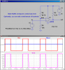
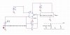
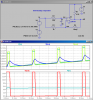
I am working on an amplifier circuit with an OPAMP which only has positive voltage supplier, +15V. The input signal is a series of positive pulses with 2.5V DC offset. I would like to amplify the pulse itself and remove the DC offset, so that the output can be used to feed other logic circuit directly.

I appreciate if any one can give me any tip to accomplish it.
 
Is it just level shifting you need?

If so this is probably better done with discrete components or a comparator.
 
Can you just use an ic chip comparator like an LM339 with the - input biased to 2.5+ΔV, where Δ depends on your application?
 
Thanks guys!

I need to explain more. The input signal comes from another charge amplifier which is powered by +15V also. So 2.5V DC offset is actually induced to make the charge amplifier working, and charging generated pulses should be very small. i would like to amplify the pulses, or pulse shaping to make full use of the dynamic range, then feed to an comparator/logic for processing.

Any tips are welcome!
 
Please post a schematic.

Sorry but your explanation is far too woolly.

Think about how much information you'd require if someone were asking you to design what you've already done.
 
Will this work?
 

Attachments

  • D90.png
    D90.png
    32.6 KB · Views: 200
Thanks Mike & Hero999,

I would not like to use comparator directly, since the dynamic range will be reduced dramatically. The schematic along with the expected output waveform are being attached.
 

Attachments

  • schematic..JPG
    schematic..JPG
    39.4 KB · Views: 204
I would not like to use comparator directly, since the dynamic range will be reduced dramatically. The schematic along with the expected output waveform are being attached.
Why do you say the dynamic range will be reduced? I thought you just wanted to convert the pulses to a standard logic level which a comparator will do.
 
I don't understand the problem.

Surely the pulses just need to be converted to a square-wave.

The DC can be removed with a decoupling capacitor and a transistor and pull-up resistor should do a good enough job of converting it to a squarewave. If you need it to be non-inverting, just use a NPN and PNP level shifter.
 
Why do you say the dynamic range will be reduced? I thought you just wanted to convert the pulses to a standard logic level which a comparator will do.

Theoretically, setting a threshold with a comparator can convert pulses to the standard logic. But the amplitude of pulses are small and varying. With environment changing (temperature etc), the DC offset and comparator threshold will drift, the amplitude of pulses will change also. To make the final output consistent, I prefer to enlarge the amplitude before going to the comparator.
 
Here is a self-biasing comparator. Even if there is slow drift in the dc level that the pulses ride on, it auto adjusts its trip point.
 

Attachments

  • D90.png
    D90.png
    35.3 KB · Views: 174
What is the smallest pulse you need to detect?
 
Status
Not open for further replies.

Latest threads

New Articles From Microcontroller Tips

Back
Top