Electro Tech is an online community (with over 170,000 members) who enjoy talking about and building electronic circuits, projects and gadgets. To participate you need to register. Registration is free. Click here to register now.
Welcome to our site! Electro Tech is an online community (with over 170,000 members) who enjoy talking about and building electronic circuits, projects and gadgets. To participate you need to register. Registration is free. Click here to register now.
You can look at the op amp (connected properly) as a sort of automatic balancing machine where the output tries to force one of the inputs to be equal to the other.
In real life circuits however there is usually a small imbalance that already exists, in the form of an offset voltage called the input offset voltage. This is usually small like 1 to 10mv but in some special design op amps it can be as small as 1uv. There is another problem however, in that the polarity is not known and can be either plus or minus, so that 1mv might be +1mv or -1mv.
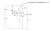
With your circuit constructed from resistors that are exactly precise and exactly 3.000000 volts at the point you indicated, there would be 3v at the non inverting terminal and 3v at the inverting terminal and 3v at the output too, but because of the input offset voltage and the gain of the circuit we would see on the output 3v plus or minus the offset voltage times the gain.
The offset voltage 'acts' very much like a small battery in series with one of the input terminals, and this battery can be either plus or minus in polarity. One way to better understand the circuit is to redraw it with a small battery say in series with the inverting terminal with the positive terminal connected to the 2k resistor. You can then analyze the circuit and find that the output voltage has to go up to a slightly higher voltage than 3v to compensate for this small battery voltage. The output voltage ends up going up to about 3v plus the offset times 50 which would bring it up to 3.050 volts in this case (with 0.001v offset and gain=100k/2k). Note however that if the input offset happened to be of opposite polarity (battery with minus terminal connected to the 2k resistor) then the output would have to go DOWN by Voffset times the gain, which would bring it down to 2.950 volts.
The above analysis is an approximation and to get it exact we would have to regard the 100k and 2k as a voltage divider, which means a 1mv offset would really cause a 51mv output change rather than a 50mv change, but the basic idea is apparent.
hi,
Thats the AC gain.
The clue is in the note saying that the voltage at the junction of the cap and input resistor is +3V.....
So you have +3V on the NON inverting input and +3V on the Inverting input.
The DC gain of the non inverting input is +G=1 + 1
the DC gain of the inverting input [because of the presence of the cap] is 1
So what is the algebraic sum of these two values.????
This site uses cookies to help personalise content, tailor your experience and to keep you logged in if you register.
By continuing to use this site, you are consenting to our use of cookies.

")