Continue to Site

Welcome to our site!

Electro Tech is an online community (with over 170,000 members) who enjoy talking about and building electronic circuits, projects and gadgets. To participate you need to register. Registration is free. Click here to register now.

  • Welcome to our site! Electro Tech is an online community (with over 170,000 members) who enjoy talking about and building electronic circuits, projects and gadgets. To participate you need to register. Registration is free. Click here to register now.

opamp adder amplifier

Status
Not open for further replies.

mif_tronics

New Member
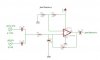
when i was experimenting with adder amplifier circuit (using op amp UA741), i found something inadvertently .. when i put 2 AC sources, 40KHz(at about 8Vpp) and 36-44KHz(at about 1.4Vpp), i got the difference (beat)frequency between both sources. the output amplitude got smaller as the difference frequency became small.
as long as i know, difference frequency can be obtained by using modulator circuit. mid signal operation in nonlinier circuit yields 4 harmonic frequencies, f1, f2, f1-f2, and f1+f2. beat frequency can be obtained by filtering modulator output.
here i enclose the scheme.

i dont know how it could yield beat frequency as i know no nonlinier circuit there..is there anybody can help me?
 

Attachments

  • adder amp.JPG
    adder amp.JPG
    20.2 KB · Views: 899
It's an audio mixer, so you get the beat difference out just as you would expect.

Have you ever tuned a guitar?, you hold down a certain fret and pluck both that string and the one next to it - adjust the tension of the string for zero beat, EXACTLY as the mixer above works, except it's mixing in the air and in your ear.
 
It is most certainly non-linear at those frequencies. The output can't keep up with the inputs. The slew rate is 0.5 V/usec.
 
Last edited:
Your circuit is not a normal adder (summing) circuit.

First, if you want to add two signals with an inverting op amp configuration you normally use two separate input resistors in place of R1. That isolates each input. In your circuit, each signal output is trying to drive the other output through the two input capacitors, C2 and C3. Normally you don't want to drive an output with another signal.

Second, C1 has no useful purpose. You generally want to keep the capacitance at an op amp's inverting input as low as possible to avoid peaking in the response. C1 will add a very large peak to the amp response.

If C1's purpose was to low-pass filter the signal then add it across R2. Alternately, split the input resistor(s) into two equal resistors (1/2 the value of the total) and connect a capacitor(s) to ground from the junction between each set of the two series resistors.
 
i ve no experience in audio circuit....
so you mean that my circuit acts as mixer?! but why does there is only beat frequency as output as the biggest signal in amplitude? does the RC on inverting input work as a lowpass filter (bypassing all the basic frequency sources to GND)? i really didnt mean that..:p
about the nonlinierity, can i draw a nonlinierity curve like transistor one(Ic vs VBE)? in what parameter is the curve drawn(X axis & Y axis)?
 
I think he's saying it's a mixer (a linear addition) rather than a modulator (a linear multiplier). These beat frequencies might be a form of intermodulation--a common side-effect of mixing signals in a non-linear medium.
 
Last edited:
The lousy old 741 opamp has trouble above only 9kHz. Your frequencies are too high for it.

Your fairly high input signals are probably saturating the input transistors of the opamp.

No wonder it is non-linear.
 
The lousy old 741 opamp has trouble above only 9kHz. Your frequencies are too high for it.

Your fairly high input signals are probably saturating the input transistors of the opamp.

No wonder it is non-linear.

You know, I think the only market out there for the 741 is the college kids in their university labs... there must be untold numbers of these things sitting in drawers waiting to be employed in some lab experiment. Think of how much time would be saved if there were better opamps in those drawers.
 
I would think that they're mainly used for legacy products.

I've got loads of 741s in my junk box and they normally get used on experimental circuits so I don't have to risk a decent op-amp. The only time I use them for a real project is when it's something like a low speed DC amplifier like a power supply.
 
after having more experiments i can ensure that the beat frequency wasnt produced by 741's nonlinierity! i found that frequency on sources junction point. C1 bypassing all of higher frequencies to gnd.
if i put a resistor on both source output (so the circuit works a mixer) it didnt work as before, no beat frequency there.
so my conclution is that my 2 AC sources r operated in AND gate or something like that.
 
You have the outputs of the ultrasonic generators directly AC shorted together. Then they are very non-linear.

Your "filter capacitor" is not a filter. The capacitor is at the "virtual ground" input of the inverting opamp where there is no signal voltage.
 
Have you using ceramic AC coupling capacitors?

Ceramics are very non-linear so it would be no surprise if they're responsible for the modulation.
 
i dont know how it could yield beat frequency as i know no nonlinier circuit there..is there anybody can help me?

First of all, that schemo is totally wrong if that thing is supposed to be a linear adder. Another big part of the problem is right here: "at about 8Vpp". You're using a 12Vdc supply, and that limits the device to somewhat less than 12Vp-p swing. You're overdriving it, and that means big-time nonlinearity.

Then there are incidental nonlinearities since the 741, with a dV/dt= 0.5V/uS, isn't exactly the peppiesy op-amp out there, and doesn't handle extreme frequencies very gracefully. That, too, is going to lend some IMD to the output mix.
 
i agree whether 741 is nonlinier at that frequency, but i think that's not the main cause.
why do shorting the outputs of the ultrasonic generators directly AC together cause a very non-linear result? i used polar capasitors there. i think that it bypassing the higher frequencies cause when i O'scope there were many signal at virtual gnd.
 
i agree whether 741 is nonlinier at that frequency, but i think that's not the main cause.
why do shorting the outputs of the ultrasonic generators directly AC together cause a very non-linear result?
The 1uF capacitors in series make a 0.5uF capacitor that each ultrasonic gemerator is driving. When one output tries to go positive when the other output tries to go negative then the load imedance for each of them is only the reactance of the capacitor. 0.5uF at 40kHz is a reactance of only 8 ohms which is like a dead short to each generator. So their outputs are very distorted (producing many harmonics). Look at each output on your 'scope.

i think that it bypassing the higher frequencies cause when i O'scope there were many signal at virtual gnd.
The virtual ground has many signals because the old 741's output cannot keep up at such a high frequency for it to cancel the input signals.
 
Status
Not open for further replies.

Latest threads

New Articles From Microcontroller Tips

Back
Top