Continue to Site

Welcome to our site!

Electro Tech is an online community (with over 170,000 members) who enjoy talking about and building electronic circuits, projects and gadgets. To participate you need to register. Registration is free. Click here to register now.

  • Welcome to our site! Electro Tech is an online community (with over 170,000 members) who enjoy talking about and building electronic circuits, projects and gadgets. To participate you need to register. Registration is free. Click here to register now.

op-amps driving NPN's to limit voltage and current

Status
Not open for further replies.

arhi

Member
I was never good with analog stuff so if mine idea is wrong from the beginning feel free to let me know :D but if it can be modified to work, I'd really appreciate the help.

The idea follows ...

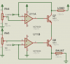
RV5 is simulating the output from a DAC that sets the limit for the current of the PSU
RV4 is simulating the output from a DAC that sets the limit of the output voltage of the PSU
U11 is a rail2rail op-amp and part B on the inverted input gets the I-Sense (from the shunt resistor on the PSU output) and part A gets the V-sense (from the voltage divider from the output of the PSU - the voltage comes)

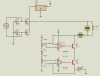
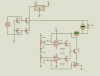
What I want to achieve is to set limit for current and voltage using 2 dac's (in this case RV4 and RV5) and drive the NPN that will control the output. In the attached image load is driven directly with two npn-s but for the final design I want this 2 to drive bunch of MJ802 or similar in parallel .. for the NPN drivers I'd use some npn's with 4A, beta=750 (BD681 as I have bunch of those) but for starters this thing should work (up to 4A) with only this two transistors.

Can someone tweak up this part of the schematic so that it works :D .. I'd like to keep mcp602x as op-amp and this BD681 as a driver ... I want to drive the negative rail and not positive rail on the output ...

Any ideas?
 

Attachments

  • screenshot8.png
    screenshot8.png
    10.9 KB · Views: 283
on the other hand, I'm not 100% sure where is best to fetch the voltage measurement from ?

The way I see it - the potential difference on the LOAD is created not by moving the + rail closer or further from GND but actually oposite, the - rail is moved closer or further from GND while + rails stays on the same potential related to the gnd... this is why I'm taking vsense from the negative output terminal and not from the positive one.... I might be going wrong about all this but .. that's why I'm asking question and not presuming I know everything (I'm pretty aware of holes in my knowledge of electronics)

Check the attached image for "block" schematic of the whole device
 

Attachments

  • screenshot3.png
    screenshot3.png
    13.8 KB · Views: 220
maybe something like this would be a better choice ... but I fear I have chosen a wrong op-amp and that these mcp's will not do it ..

btw I want to control the "lower side" and not the "top side" of the potential because this way the "body" of the transistor can go directly to heatsink without need to add an insulator between transistor and heat sink (as heat sink is exposed)
 

Attachments

  • screenshot4.png
    screenshot4.png
    14.8 KB · Views: 304
Seems like it should work. Positive rail regulators always play with your mind. Have you simulated it?
You do of course need some filter caps.
 
Arhi, on you last circuit, how does the NPN transistor get its base current?

Where is the filter capacitor?
 
Last edited:
Seems like it should work. Positive rail regulators always play with your mind. Have you simulated it?
You do of course need some filter caps.

I hope it will .. have not simulated it yet .. I think I might have to find some other op-amps ... will have to do some testing locally to see how much will I be able to open BD681 with mcp602x (simulation will never show real data there as everything is "ideal" - not to mention proteus don't have model for BD681) as I fear I'll have to use some high voltage op-amp (LT1013 or LT1014 comes to mind) ...

anyhow I think the major problem I had that I tried to solve with 2 transistors will be solved with this 2 diodes and 1 transistor ..
 
I've used two op-amps for current and voltage limit on a power supply, using the two diodes, like your circuit in post #5. You need a pull-up resistor to provide the base current, and then either of the op-amps can pull the base low.
 
Arhi, on you last circuit, how does the NPN transistor get its base current?

damn i missed that :D ... there should be 1K res between B and C of that transistor


Where is the filter capacitor?

this is just a "block" schematic .. the full schematic has bunch of capacitors right after gretz, bunch of them parallel to the load .. there's a mcu, dac, pga, display ... all not really relevant to this part that I don't know how to make :)

edit, also the AC source is 6, 18, 24, 32VAC and there's bunch of relays to change what AC source is in use so I can reduce heat dissipation (not to make 2V output out of 40VDC by heating my house :D )
 
Last edited:
I've used two op-amps for current and voltage limit on a power supply, using the two diodes, like your circuit in post #5. You need a pull-up resistor to provide the base current, and then either of the op-amps can pull the base low.

Thanks .. I forgot the res between B and C there .. I just need to figure out the size of it ... BE voltage on this bd681 is 2.5V iirc (not standard 0.7, probably because it's few transistors inside single pack and not only one .. that's why it's beta is 750+) ... and I need to figure out the op-amps .. can I use this mcp's or in this case I need to use op that will be powered from + rail
 
Even the LT1013 won't quite do it with the 38volt (RMS?) input voltage. I think it is 44 volts maximum. It also has to sink your base current, but we don't know what your output current needs to be yet. You may need one more transistor to power things up.
 
most power supplies do their sensing and regulation on the high side of the load. open-frame power supplies usually have sense lines to measure the voltage at the load. the current measurement for the current limiting is done across what's usually a 0.1ohm or 0.001 ohm emitter resistor for the series pass transistor. the voltage and current sense lines feed a pair of op amps, one measures the voltage at the load, the other measures the current. these op amps control the series pass transistor. both the output voltage and current can be set with potentiometers that change the reference voltages of the op amps. this is all done on the high side of the load, not the low side, because everything knows where "ground" is, but your circuit doesn't know where the supply voltage is, and doesn't sense it at all. some things that regulators do is actively filter out noise. you can't do that on the low side of the load, because you can't see what noise or other variations in the supply voltage may exist. even if you did, those variations and noise exist on the high side of the load, and that's where you remove them, rather than the low side, where all you're accomplishing is to make the load float from ground.
 
ronv, the lt1013 was the first one that came to mind, yes one that can take 45V is needed ... as for the current it is un-important as after this bd there's most probably another one and then 10 high power transistors to give out needed current .. but that part is "simple", I'm attm trying to solve the driving part

unclejed613, yes, but when you do regulation on the low side you can attach the body of the transistor on the bare metal of the heatsink ... while if you are doing it on the high side you have to insulate transistors and add to the thermal resistance from junction to the air. as for the other high vs low side regulation, check out the https://www.electro-tech-online.com/custompdfs/2011/02/psu30V-5A.pdf it is schematic that works for over 15 years .. I know more then 50 ppl that built it .. works like a charm... only it is analog and I want to make one that is fully controllable via mcu
 
actually, you need to look at an op amp based design. modifying the transistor design you referenced without knowing where to assign the DAC outputs and reference/diff voltages is going to be a real pain to modify. the design in the attachment uses op amps for the voltage reference and the current sensing, and is closer to what you're looking for. keep in mind that you're feeding the DACs from a digital source, and the stability of your ground is extremely important. using low side regulation will defeat this stability, because your ground will be floating. just because a self-contained low side regulator works fine, doesn't mean it will behave well when interfaced with external control equipment
 
Last edited:
keep in mind that you're feeding the DACs from a digital source, and the stability of your ground is extremely important. using low side regulation will defeat this stability, because your ground will be floating

This is a part I completely ignored !!! Thanks a bunch for pointing this out. I did already make a mock-up of the low side regulator that works (not as good as I'd like but works) with similar design as my last attachment but with pots instead real dac output and I have some fluctuations that were not cleat to me... and then I set the low side of the pot to the floating gnd but ... I can't do this with a dac .. it ain't gonna work .. so .. I'll have to drive positive side ... that one I made once already, it is fairly simple :) ... thanks for preventing me to waste more time :D
 
Status
Not open for further replies.

Latest threads

New Articles From Microcontroller Tips

Back
Top