Continue to Site

Welcome to our site!

Electro Tech is an online community (with over 170,000 members) who enjoy talking about and building electronic circuits, projects and gadgets. To participate you need to register. Registration is free. Click here to register now.

  • Welcome to our site! Electro Tech is an online community (with over 170,000 members) who enjoy talking about and building electronic circuits, projects and gadgets. To participate you need to register. Registration is free. Click here to register now.

op-amp

Status
Not open for further replies.

ujjvalshah

New Member
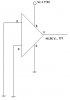
i have an op amp (LM358N) which i think is behaving wierdly

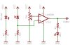
i have just connected a 9 volt (little drained.. now 7.9volts)
i am not giving any input and still its giving around 6.5 volts at the output pin....

whats wrong with it or am i making some mistake.....


pls help!
 
A circuit diagram would be most helpful. Generally speaking an unconnected high impedance input can go to whatever voltage it wants. If this is even a few microvolts different from the other input then the output will go to the supply rail. There's no such thing as unconnected inputs in opamps. Connect them, or be prepared for the behavior you observe.
 
Please post the schematic.

If your circuit is designed properly it should operate from 7.9V with no problems.
 
heres the schematic....


i guess there is some problem with the op-amp...
 

Attachments

  • schematic.JPG
    schematic.JPG
    9.6 KB · Views: 428
There is a problem with the op-amp, the problem is you haven't connected it up correctly.

What's it supposed to do?

That circuit won't work, as both the inputs are connected to 0V, which for a start is probably out of their range and secondly an op-amp won't do anything if you connect both of it's inputs to the same voltage. In theory the output will read 0V but in practice it'll read some random voltage as the common mode rejection ratio isn't perfect and it has a heck of a load of gain.
 
hmmm.. kk

heres what i had tried initially..... (pls check the schematic)
i had the same problem ..ie 6.5 volts as output. .irrespective to wether i expose the photodiode to light or not.. so then i tried removing the inputs (which was quite stupid i guess)

actually what i want to do is make an ir sensor and want to drive a microcontroller pin high when it receives any ir rays....
can you pls post any link or any schematic for it....

and what should i use .. what will be appropriate for my application.. a phototransistor or a photodiode?

thanks.....
 

Attachments

  • Sensor%20Schematic.jpg
    Sensor%20Schematic.jpg
    52.3 KB · Views: 966
Like I said on the other forum, the opamp doesn't have any negative feedback to control its gain so the input offset voltage (7mV max) is amplified about 100,000 times. It is an LM358 that works when its input voltage is at its negative supply voltage.

I also said thet the IR is not modulated so the IR sensor diode will pick up IR from warm things, light bulbs and sunlight.
 
I once did a circuit like that, with a phototransistor, but the phototransistor is wired to the (-) input and the pot to the (+) input, and I also used an LM339 comparator (I think it was LM339, not sure).
 
and what should i use .. what will be appropriate for my application.. a phototransistor or a photodiode?
I haven't read your other forum, so please forgive any lapse from partial information.

It looks to me like you're building a sensor, expecting ON/OFF information. LM358 isn't a good part for this. You should choose a comparator instead. Consider adding hysteresis to the comparator circuit.

A phototransistor is more sensitive but generally slower. A photodiode is usually less sensitive but can be extremely fast. If you're using LM358 or LM339, the phototransistor will usually be fast enough if you need the sensitivity.

Google or Wiki the terms that I underlined and learn a lot more.
 
ujjvalshah said:
heres the schematic....


i guess there is some problem with the op-amp...


No, just a miss application. Every op-amp has a equivelent input DC offset specification, that means with both inputs grounded the input stage still sees a small DC voltage, usually some small microvolt value. It would be nice if it was a perfect 0 volts, but variation in production process means they all have some small DC offset.

If your circuit there is no negitive feed-back being applied, so the amp is working at maximum gain, maybe 60DB (X 1,000,000) so even just 6uv of input DC offset voltage would drive the output to >6vdc.

Left
 
Leftyretro said:
the amp is working at maximum gain, maybe 60DB (X 1,000,000) ...
Nope.
The LM358 with a 5V supply and a 20k load has a typical voltage gain of 100dB which is 100,000.
A voltage gain of only 60dB is only 1000.

With a 15V supply or higher and a 20k load or higher then the LM358 has a typical voltage gain of 120dB which is one million.
 
Leftyretro said:
Every op-amp has a equivelent input DC offset specification, that means with both inputs grounded the input stage still sees a small DC voltage, usually some small microvolt value.

I would say the offset is usually some small millivolt value, which is a thousand times bigger than microvolt. Only very special Opamps has offset in small microvolt value.
 
audioguru said:
Nope.
The LM358 with a 5V supply and a 20k load has a typical voltage gain of 100dB which is 100,000.
A voltage gain of only 60dB is only 1000.

With a 15V supply or higher and a 20k load or higher then the LM358 has a typical voltage gain of 120dB which is one million.

Yes I confused power DB with voltage DB scale (once again!). However my basic point to the OP was that the first posted circuit shown was operating at full gain so the input offset value, whatever it's specific value, would be shown as an offset output voltage = input offset X opamp gain. Agreed?


Lefty
 
The input offset voltage for the LM358 opamp (with both its inputs grounded)could make its output voltage positive, or try to make its output voltage more negative than ground, then it would be 0V if it didn't sink any current.
 
Status
Not open for further replies.

New Articles From Microcontroller Tips

Back
Top