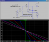
I know that with the circuit shown below, I can vary the gain from -1 to +1 with the potentiometer.
**broken link removed**
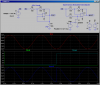
If I change the resistor directly above the op-amp from 10k to 20k, would that make the gain variable from -2 to +1 ? Is there a convenient formula for this kind of circuit (variable gain op-amp)?
**broken link removed**
If I change the resistor directly above the op-amp from 10k to 20k, would that make the gain variable from -2 to +1 ? Is there a convenient formula for this kind of circuit (variable gain op-amp)?

")