The load is a high impedance analogue input unit for some PLC.
When i say grounded my load, i connected both the lower end of the load and pin 5 both together with ground. When i do so, the readings fall to zero. Thats with a resistor to simulate the load. Have not tried with the load before.
For the capacitor, i used the largest value i could find...im going to try a lower value to see.
Th gain is fine i think i initally thought i need a larger value for the I/O to sense. But it seems to be alright. So i only need to stablise it.
The scopes ground? I never conected anything to it. For the voltage part, i got the idea from one of the samples. Pic 2. Arent they using like 3v for reference?
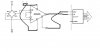
What i have now is PIC 1(the uglier one).
When i say grounded my load, i connected both the lower end of the load and pin 5 both together with ground. When i do so, the readings fall to zero. Thats with a resistor to simulate the load. Have not tried with the load before.
For the capacitor, i used the largest value i could find...im going to try a lower value to see.
Th gain is fine i think i initally thought i need a larger value for the I/O to sense. But it seems to be alright. So i only need to stablise it.
The scopes ground? I never conected anything to it. For the voltage part, i got the idea from one of the samples. Pic 2. Arent they using like 3v for reference?
What i have now is PIC 1(the uglier one).