ElectroChas
New Member
Hi all,
Here goes my first post here ...
First off, thank you for having me as a member to this forum.
I am looking for some assistance regarding a simple op-amp circuit.
I included 2 urls showing the same exact cirucit, but neither of them specify the values for the voltage divider resistors, or the timing resistor or capacitor.
I will mention that neither url I posted is in any way an advertisement and both sites are reputable and have been online for years.
**broken link removed**
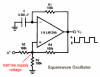
Square Wave Generator
Basically I have 2 questions about this circuit that have been daunting me for the better part of a week.
Both sites show the image of the square wave supposedly generated by this circuit, yet nothing I have tried regarding resistance and capacitance values comes close with regards to duty cycle and the negative component of the wave.
1 Assuming the waveform image is in fact reasonably accurate, what values will give me the pulse that has a negative DC component and reasonably symetrical highs and lows?
I do not seek, nor expect a perfect 50% duty cycle, but the images shown do appear to represent something to that effect.
My own personal experience with op-amps has generally involved the circuit having 0 or 1 feedbacks and at least 1 rail from the power source directly or indirectly connecting to the inverting or non-inverting input of the op-amp. But as you can see, this circuit has dual feedback and only connects to the power source through the Vs+ and Vs- pins of the op-amp chip.
2 What is the starting point for the circuit? In other words, what initially begins the output for the circuit so the feedback paths begin to work?
Additional notes ..
When I build this circuit and use a oscilloscope on the output, what I get is very low positive duty cycle square wave.
If I use values on the non-inverting input side that cause a higher capacitor charge time (low frequency pulse), I do get a waveform that shows the sawtooth positive component and sawtooth negative component with the oscilloscope's AC mode on the scope and in the DC mode the wave is basically square with no negative component. If I go with a lower charge time (higher frequency), I get square waves that do not have a negative components in either mode and always seem to have a very low positive duty cycle.
I can gladly post scope images upon request if it can help answer these questions.
Thank you for reading,
Charles
Here goes my first post here ...
First off, thank you for having me as a member to this forum.
I am looking for some assistance regarding a simple op-amp circuit.
I included 2 urls showing the same exact cirucit, but neither of them specify the values for the voltage divider resistors, or the timing resistor or capacitor.
I will mention that neither url I posted is in any way an advertisement and both sites are reputable and have been online for years.
**broken link removed**
Square Wave Generator
Basically I have 2 questions about this circuit that have been daunting me for the better part of a week.
Both sites show the image of the square wave supposedly generated by this circuit, yet nothing I have tried regarding resistance and capacitance values comes close with regards to duty cycle and the negative component of the wave.
1 Assuming the waveform image is in fact reasonably accurate, what values will give me the pulse that has a negative DC component and reasonably symetrical highs and lows?
I do not seek, nor expect a perfect 50% duty cycle, but the images shown do appear to represent something to that effect.
My own personal experience with op-amps has generally involved the circuit having 0 or 1 feedbacks and at least 1 rail from the power source directly or indirectly connecting to the inverting or non-inverting input of the op-amp. But as you can see, this circuit has dual feedback and only connects to the power source through the Vs+ and Vs- pins of the op-amp chip.
2 What is the starting point for the circuit? In other words, what initially begins the output for the circuit so the feedback paths begin to work?
Additional notes ..
When I build this circuit and use a oscilloscope on the output, what I get is very low positive duty cycle square wave.
If I use values on the non-inverting input side that cause a higher capacitor charge time (low frequency pulse), I do get a waveform that shows the sawtooth positive component and sawtooth negative component with the oscilloscope's AC mode on the scope and in the DC mode the wave is basically square with no negative component. If I go with a lower charge time (higher frequency), I get square waves that do not have a negative components in either mode and always seem to have a very low positive duty cycle.
I can gladly post scope images upon request if it can help answer these questions.
Thank you for reading,
Charles
")