Continue to Site

Welcome to our site!

Electro Tech is an online community (with over 170,000 members) who enjoy talking about and building electronic circuits, projects and gadgets. To participate you need to register. Registration is free. Click here to register now.

  • Welcome to our site! Electro Tech is an online community (with over 170,000 members) who enjoy talking about and building electronic circuits, projects and gadgets. To participate you need to register. Registration is free. Click here to register now.

Op amp selection

Status
Not open for further replies.

goolash

New Member
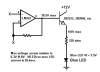
I am trying to decide what sort of op amp to use for an LED lighting project. It is a variable 6-12 Vdc to 3.5-0 Vdc very slow changing signal conversion (the 6-12 Vdc is an analog signal created by a temperature sensing device), so I have no bandwidth requirements, but the opamp needs to use +12Vdc/gnd as the supply voltages, and 12Vdc reference and input. They will be driving a 3.5 V forward voltage, 30 mA forward current LED. The response requirement is slow enough that I can use a second or third op amp in parallel to provide extra current capacity to drive the 30 mA LED at full on.

I'm limited at the moment to what I can pick up at radioshack or similar, LM741, LM324 quad, TL082/TL082CP dual, or LM339 quad comparator.
 
Post a schematic. It will help eliminate misunderstandings. None of those OpAmps are the so called rail-to-rail types, which it appears you want, but may not need.
 
I'll scan them and put them up, once they're in a legible state. I doubt I'll need rail-to-rail. I plan on supplying +12V only, with the V- connected to ground. The output voltage will range from 0 to 3.5V only, to drive a 3.5V LED. If it can't quite output 0V exactly, that's fine, this project does not require any level of high precision, just a ramping voltage.
 
**broken link removed**

There it is. The purpose of the overall design is to gradually dim a blue LED as Vf rises from 0 to 6Vdc, while gradually brightening a green LED, then gradually brighten a red LED from 6 to 12Vdc, while gradually dimming the green LED. The net effect will be a changing color that runs the color spectrum.

The input labelled 12Vdc is a constant, regulated 12V power supply, which will also supply 12V to the + supply pins on the op amps.

This is still a rough drawing by all means, and amongst other things I'm wondering if the auctioneering diodes are necessary or not, and whether I should go for resistors in the megohm range instead of k-ohm. I should have spent more time studying op amps back in my electronic fundamentals course.
 
The circuit isn't going to perform as you expect due to a few different things:
The blue green and red LEDs will not output ANY light at 1V, so there will be no gradual shift in brightness below a certain voltage. You'd need to determine the minimum voltage for the minimum brightness first. A better method would be to drive the LEDs with a variable current source of 0-30ma.
Referring to the "blue" circuit at the top, U2 is connected wrong for a buffer. The output of U1 should goto U2s + input only and U2s output should connect to its own - input. The + & - inputs, on the same OpAmp, should not be connected together. U4 and U6 are also wrong and should be fixed the same way. Instead of an OpAmp buffer, I would use a transistor to boost the current for the LED.
You should also drive the LED through a current limiting resistor to convert the voltage output of the OpAmp to a varying current.
The green LED will never dim as the voltage rises past 6V.
 
Yeah, I've been seeing some of these things in a cheap java-based circuit simulation I've been running. How large of a resistance would be good to put in front of the diode? Enough to draw the full forward current at 12Vdc?
 
Since the OpAmps aren't rail to rail, the max output voltage will less than the supply voltage. The LM324, as an example, typically has a max output 1.5V less than the supply voltage (10.5V for 12V supply) when sourcing apx 5ma. Here is an example of using a transistor to boost the OpAmp's max current and a resistor to limit the max LED current:
 

Attachments

  • InTheBuff.PNG
    InTheBuff.PNG
    10 KB · Views: 252
Ok, so I took your suggestions, and with the help of a java-based circuit simulator, came up with the following:

**broken link removed**
With input @ zero.

**broken link removed**
Input at 6Vdc.

**broken link removed**
Input at 12Vdc.

I notice already that I forgot to tie in one of the 12Vdc references, so I will have to go back and re-calculate the op amp resistors, but this seems to demonstrate that it's possible.
 
Well, the simulations all panned out, but when I actually assembled the circuit, the op amp began operating like a switch. The output voltage is 3.4V until I reach about 4V input, and then it jumps to 10.3V. Is the LM324 the wrong op amp to be using here?

Update: nevermind, after checking and rechecking, I noticed I failed to jumper the feedback resistor to the op amp output. Now it works more like what I intended, but still does not ever turn off completely. I am assuming this is due to a small amount of leakage current across the transistor, despite being un-biased? Also, I've found that the best output obtainable on the LM324 using a 12V Vcc is about 10.3 Vdc, so I will be recalculating my resistors for that value.
 
Last edited:
here is maybe a better solution

while not using an opamp this circuit does what your asking.
instead of using one multi color led use a red, blue and green one.
I am designing a circuit where the leds light up a cabinet but fades from all blue to all white and a mix of both.
Electronics-Lab.com Blog 4029
 
Yeah, I was thinking about that, but I don't know how to write assember, nor do I have any means of burning my own proms.
 
if you are planning on building

I have the expresspcb file as I am using same circuit for my cabinet lights that fade from white to blue and combo.
using 32 leds total (8 per array x 3 arrays
 
MrDeb,
I don't think that is what goolash is looking for. He wants the LED to change color as the voltage from a temperature sensor varies. ie: the LED changes color with temperature.
 
Status
Not open for further replies.

Latest threads

New Articles From Microcontroller Tips

Back
Top