Continue to Site

Welcome to our site!

Electro Tech is an online community (with over 170,000 members) who enjoy talking about and building electronic circuits, projects and gadgets. To participate you need to register. Registration is free. Click here to register now.

  • Welcome to our site! Electro Tech is an online community (with over 170,000 members) who enjoy talking about and building electronic circuits, projects and gadgets. To participate you need to register. Registration is free. Click here to register now.

Op-amp problem

Status
Not open for further replies.

hereward

New Member
Hi Folks,

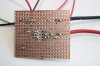
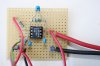
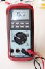
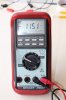
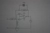
In the past I have made a few inverting op-amp circuits with gains of 10, 50 and 100, these have worked OK. One that had been working for 5 years had a copper track peeling so I tried to make a replacement. I can breadboard circuits that work but when I solder them up I have been getting erratic readings and the meter would not zero. The track did eventually break and I had no choice but move all the components to another part of the same board, in spite of the fact it had worked OK for 5 years it would not now work. The problem, I suppose, is thermocouples at the solder joints, but I wonder why I didn’t get this problem before. I have tried a few things to overcome this problem without success, the latest was to solder resistors and wires directly to the IC, cutting out the usual IC socket and using prototype board without copper pads or tracks. The meter fluctuates between zero and 1.2 mV initially. It does amplify 1 mV to around 100 mV but of course includes the initial offset. Any suggestions for a solution? – Many thanks.
 

Attachments

  • 010.JPG
    010.JPG
    3.6 MB · Views: 233
Cant comment on your building techniques.

To minimize offset, the 1Ω resistor should be equal to the parallel combination of 1K and 100K. 1K*100K/(100K+1K) = 990Ω (1000Ω would be close enough).
 
Last edited:
Hi,

You might also take some pics of the actual board so we know what you are dealing with here. The board layout may be at fault or it could be something else more simple like mismatched resistor types.

If you suspect thermal problems, perhaps you can try some freeze spray or ice. Cool something with the spray or ice and they touch it to different points while it is still cool, or something similar. See if any voltages change.
You could also try packaging it in something like a styrofoam cooler with the top closed. That would eliminate air currents from causing an alternating cooling/heating effect.

It sounds pretty high though, so maybe it is something more simple. If it was 50uv i might think it was due to bad thermal setup, but it's much higher so it sounds more like something is really wrong somewhere. Maybe there is some chemical left on the board or something.
 
Thanks for the reply MikeMl, originally when finding out how to build the circuit it was stated that resistor 3 was there as a thermal balance with the input resistor no value was given, I have actually tried other resistors including a 1k, still no joy.
MrAl thanks for that, I must have made about 10 different boards by now, will see if I can take some pictures, and try your freezing idea. The working op-amps are in their own enclosures to ensure a stable climate. Strange how the breadboard version works fine, I have tried allsorts to stop it working, like increasing the input joints, still works though.
 
There a no bypass capacitors. Usually 0.1 uf near the IC at the supply pins unless the datasheet suggests someting else.

A breadboard has unwanted capacitance, but in your case could have helped you.
 
Last edited:
Thanks for the reply MikeMl, originally when finding out how to build the circuit it was stated that resistor 3 was there as a thermal balance with the input resistor no value was given, I have actually tried other resistors including a 1k, still no joy. ....

Have a read on this page, especially the data sheet, and AN28. Your amp is supposed to have a max offset of ±5uV, which when amplified by the closed loop gain of 100 should still be less than 0.5mV.

Are you sure that the offset isn't coming from the source?
 
Hello again,

Yes and lets not forget that 10uv amplified by 100 is 1mv. Maybe he got lucky up to this point :)
But i would not expect that to vary up and down from 0 to 1mv unless there were air drafts reaching the circuit.

Also, i wonder if any other packages were tried.
 
with the 1 ohm resistor on the noninverting input, and 1k on the inverting input, you have offset from the unbalanced input currents. change the 1 ohm resistor for a 1k (910 ohms would actually be closer to balancing out the bias currents, but 1k will work). right now you have the bias currents impressing a voltage across the resistors, 150pV on one input (+) and 0.15mV on the other (-) giving 0.14995 mV offset at the inputs. multiply that by 100 and you get 14.995mV offset. this is using the worst-case bias current values in the data sheet, but you can see how this develops offset.
 
with the 1 ohm resistor on the noninverting input, and 1k on the inverting input, you have offset from the unbalanced input currents. change the 1 ohm resistor for a 1k (910 ohms would actually be closer to balancing out the bias currents, but 1k will work). right now you have the bias currents impressing a voltage across the resistors, 150pV on one input (+) and 0.15mV on the other (-) giving 0.14995 mV offset at the inputs. multiply that by 100 and you get 14.995mV offset. this is using the worst-case bias current values in the data sheet, but you can see how this develops offset.

Hi there Uj,

I agree that most op amps need the right resistor there. But arent the input currents very low for this op amp? I'll have to check the data sheet i guess as i assume you did.

But then how do you explain the fact that the offset appears to drift up and down from 0v to 1mv at the output? I assume that is what he meant in his post, that is was varying like that. Could it be air currents reaching the device and therefore altering the input offset current, by that much?
 
Thanks guys for your input it is much appreciated. I selected that op-amp because it had the lowest input offset, after ploughing through a pile of data sheets. The precautions, on the data sheet, to maintain accuracy, were daunting but mainly not required. Originally after realising that the circuit was doing what it was supposed to do, I had to abandon the plugs and sockets at the input and wire the input directly to the board, to avoid the Seebeck effect. Also there were problems with electrochemical and thermoelectric generation, latent current drift at the PSU and current distribution, but that circuit as it stands never actually caused a problem. Some circuits, I read, do not breadboard successfully because of stray capacitance; I’ve put caps across all the resistors and each side of the input resistor and to ground also one parallel to resistor three and one from output to ground. Like everything else tried it has either made no difference or made things worse. During construction I cleaned each solder joint with a spray that was so volatile it caused the board to frost over. I masked each joint and sprayed this stuff on; it just sent the meter haywire. That’s the answer: “My luck just ran out.” I don’t think I am going to crack this problem it’s time I gave up. Many thanks anyway.
 
do you need a high impedance input or low impedance? are you using this as an electrometer, for something like Ph measurements? if so, an inverting amp isn't the way to do it. with the circuit as-is, you have an input impedance of 1k, because the inverting input is a virtual ground. from what you have said so far, even the tiny bias currents for this particular op amp will give significant errors, so to begin with you should change the 1 ohm for a 1k. yes if the input stage of the op amp undergoes sudden thermal shifts, your offset will drift a lot.

your cleaning sprays may either be hygroscopic, or conductive, or come out of the can cold enough to cause condensation from airborne moisture (or, all of the above....)
 
Hi again,

Too bad it sounds like he gave up. I'd like to find out what caused the 'variation' in offset. If the IC chip was damaged that would do it.
 
In that last posting (the one that didn’t arrive) I referred to KISS’s post about the power supplies needing capacitors. This was new to me, as is evident from Nigel Goodwin’s sticky the power supply isn’t given much detail and most times omitted altogether. I had used two 9V batteries to replace the mains power supply in case this was causing a problem, it didn’t help. I wouldn’t have thought a battery supply would have a ripple problem, but then I don’t know much about anything. We could be on to something here; I am going to start from scratch with new components and caps across the power supplies. (The purpose of the circuit is to amplify the voltage drop across a shunt.)
 
Hello again,

Power supply bypass capacitors are almost always necessary. For this particular kind of op amp they are even more necessary because it provides it's own internal clock and other circuitry used to stabilize the input offset. In many schematics however these caps are not shown, taking it for granted that the builder knows they are important.
0.1uf caps are usually the minimum, sometimes also paralleled with a 1uf or 10uf electrolytic. The data sheet might mention this also.
 
the 0.1uf bypass caps also should be placed right at the power pins of the op amp. a picture of the board layout might also be helpful here
 
The neagative supply rail is the most affected in my opinion from experience. I had multiple instances of a vacuum guage that every 5 years or so had to have filter caps replaced. High temp and high humidity environment.

Pay attention to "close to" the op amp body for the 0.1 ceramics usually, As was said a 10 uf, particularly tantalum can be placed further away.

Bypassing can be a real art. Sometimes requiring multiple types of parallel capacitors.

What hasn't been mentioned is that rectification of RF can occur an the OP amp inputs. So, at least put it in a grounded metal box with a resistor for the input and see what happens before throwing in the towel.
 
Hi Folks,
After building the circuit with caps, and with the op-amp on quiescence the reading on the meter was 22.23 mV falling slowly for about 15mins. to 19.23mV (would not zero). After inputting 1mV from a voltage divider the reading was a fairly stable 115.1mV. The gain was about 97 whatever the initial reading. Still no joy.
 

Attachments

  • 010 - Copy (800x533).jpg
    010 - Copy (800x533).jpg
    232.3 KB · Views: 194
  • 011 (800x533).jpg
    011 (800x533).jpg
    197.4 KB · Views: 197
  • 004 (533x800).jpg
    004 (533x800).jpg
    213.3 KB · Views: 171
  • 005 (533x800).jpg
    005 (533x800).jpg
    216.1 KB · Views: 198
Status
Not open for further replies.

Latest threads

Back
Top