Electro Tech is an online community (with over 170,000 members) who enjoy talking about and building electronic circuits, projects and gadgets. To participate you need to register. Registration is free. Click here to register now.
Welcome to our site! Electro Tech is an online community (with over 170,000 members) who enjoy talking about and building electronic circuits, projects and gadgets. To participate you need to register. Registration is free. Click here to register now.
Going to be using it to control my fish tank system.
Ch1 will be connected to a Cacium Recator where the pH will be set at about 6.55. when it reaches that the solenoid valve will turn of the CO2, thereby stop it from going any lower.
This solution from the reactor will be pumped into the tank slowly, BUT people have had problems with setting it up and have offen pump too quickly, and therefore reducing the pH in the Tank to dangerious levels.
So and probe on ch2 will be placed in the tank to monitor and if neccesary overriding (switching off) the valve controlled by Ch1.
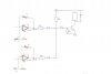
Because the input signal changes very slowly, when its at the threshold point of the opamp (against the Ref Voltage) it start to form a "square Wave" output and causing the relay to "vibrate", and not acting as a "clean" switch.
Attched is a basic schematic of the comparator and relay driver.
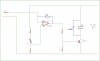
Thanks Eric, I've actually using a 2M pot for feedback, found even 1M was given to much hysteresis, also have put 2 diodes in, one across the relay and the other across the transistor, found it recommended on the data sheet.
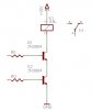
the problem now is the logic gate. Are there any AND logic ICs with only 2 inputs that can handle Vcc at 15V? (need to keep the design small) or should I just use 2 transistors in series?
Also another problem is, when the feed from the opamp is LOW Voltage is about -15V, could I just use a diode to only supply positive voltage to the Logic Gate?
supply will be + - 15V. originally used the resistors as a voltage divider to drive a transistor, but would like it to drive a logic gate dirrectly.
basically what i'm wanting to do is outputs from the opamps into the Logic IC (AND) to drive a relay. so both ouputs from the opamps must be high to turn on the relay.
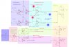
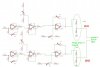
I've attached a pic of the final schematic, If you could please check and see if i've got it right, i've broken it down into coloured block to help, the "connection" points will go to a display board where it will be displayed on 3 different Voltmeters.
The threshold op-amps have a hysteresis resisters for chatter free switching.
The outputs from the pH circuits go to a AND logic to act as a safe gaurd, ensuring the tank pH is above a set limit for the relay to opperate.
Component values not shown.
PLEASE advise if I have made any error with the schematic.
This site uses cookies to help personalise content, tailor your experience and to keep you logged in if you register.
By continuing to use this site, you are consenting to our use of cookies.

")