Frosty_47
New Member
Hello,
My prof gave me a homework assignment regarding offset nulling. I know how to null using the provided offset null pins however the hmw question asks on how to null a non-inverting op-amp that does not have offset-null pins.
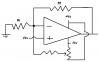
In inverting amplifier, nulling can be achieved by connecting a resistor (that must be = Rf || Ri in value) in series with GND and the non-inverting input. But, how should I connect the resistor to achieve the same thing in the non-inverting configuration?
Thanks
My prof gave me a homework assignment regarding offset nulling. I know how to null using the provided offset null pins however the hmw question asks on how to null a non-inverting op-amp that does not have offset-null pins.
In inverting amplifier, nulling can be achieved by connecting a resistor (that must be = Rf || Ri in value) in series with GND and the non-inverting input. But, how should I connect the resistor to achieve the same thing in the non-inverting configuration?
Thanks
 ) the bias voltages will be + and - 40V (80V total). OPA454 does not have any offset null pins so is it ok for me to asume that it is already nulled by the manufacturer ?