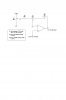
I am trying to build a meter to display pressure. I have a transducer that has an output from .53 volts at 0 psi to 4.53 volts at 500 psi. I want the meter to read 0 volts at 0 psi and 5.00 volts at 500 psi. I have used Ltspice to simulate the circuit and it shows no problems. When I build the actual circuit, the output is not correct. The readings I am getting are OK from 125 psi to 500 psi. (they are only off by about 2 psi which is close enough for me). The problem is the lower readings are off a lot more. At 0 psi the reading is .14, at 10 psi the reading is .21 and at 50 psi the reading is .57. I have tried to adjust the resistors, but this does not help. Is this because the simulator uses an "ideal opamp" and I am useing a 741 opamp? I have attached the schematic to show the values I am useing. I am a novice so please do not get too technical in your replies.
Continue to Site