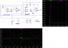
It would make sense if the circuit worked as you think it does. But it doesn't. Do the simulation, don't just talk about it.
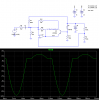
As soon as the output tries to rise about the transistor's base voltage it will start to apply voltage to the 10k resistor so as to keep the voltage at the base voltage value (in other words clamping it at that level). This will continue until the transistor saturates. Only when the transistor saturates, when the voltage at the 10k resistor reaches the reference voltage level, will the output then start to rise with a new gain value based upon the parallel value of the two feedback resistors.
Make sense to you?")
Carl,
Then it is not a clamping circuit, the gain changes as i had said all along, but it does not clamp the output to any set value.
So you see why you can not remove the 10k resistor and have it work the very same way? As i said several times, with the 10k resistor it is not a clamp, but without the 10k resistor it then becomes more of a clamp (10k shorted).
The new gain will vary from whatever 43k provides to whatever 43k in parallel with 10k will provide as the transistor conducts more and more. That's definitely not a clamping action, and it's not when the transistor saturates either. The output is free to rise more as the input signal level is increased.
I dont see how you can say there is any clamping action, that's what you are saying that i dont see, that's the only thing. Explain how the output goes to some set level and doesnt rise significantly (aside from running out of supply voltage of course).
Last edited: