i have this exam paper question.
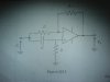
i have attached circuit diagram below
i derived
for first question
Vo= 2RC(dVi/dt) - Vi
(Vo/Vi)= 2sRC - 1
for second question
magnitude = |Vo/Vi|=|2jwRC-1|
and dont know how to find phase.
I'm not sure about my answers as i learned them from book that has no this kind a examples. so I'm glad if someone can show me how to solve this
Thanks
- derive an expression for transfer function
- find expression for the magnitude and phase of the response
i have attached circuit diagram below
i derived
for first question
Vo= 2RC(dVi/dt) - Vi
(Vo/Vi)= 2sRC - 1
for second question
magnitude = |Vo/Vi|=|2jwRC-1|
and dont know how to find phase.
I'm not sure about my answers as i learned them from book that has no this kind a examples. so I'm glad if someone can show me how to solve this
Thanks
")
