Continue to Site

Welcome to our site!

Electro Tech is an online community (with over 170,000 members) who enjoy talking about and building electronic circuits, projects and gadgets. To participate you need to register. Registration is free. Click here to register now.

  • Welcome to our site! Electro Tech is an online community (with over 170,000 members) who enjoy talking about and building electronic circuits, projects and gadgets. To participate you need to register. Registration is free. Click here to register now.

op amp amplification

Status
Not open for further replies.

Fazrifzi

New Member
hi, i'm student. i just joined here.
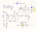
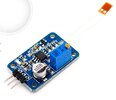
I have a strain module, but I don't know how much gain that use in this module where this module uses an amplifier. can someone provide an answer for me along with how to know the gain is calculated ? i insert 2 attachment.
I've been stuck in progress for 2 months. please help me :')
 

Attachments

  • SEN77631Y3_pro_1.jpg
    SEN77631Y3_pro_1.jpg
    156.9 KB · Views: 282
  • straingaugemodule.jpg
    straingaugemodule.jpg
    45.3 KB · Views: 279
Your attached circuit is not a strain gauge amplifier.

JimB
 
With circuits like your example schematic, with a single input to the opamp - and the opamp + input to a fixed voltage or ground, the gain at each stage is proportional to the ratio of the input resistor to the feedback resistor.

eg. The left hand part of the circuit has 10K (R6) input and 470K (R7) feedback; 470 / 10 = 47. The output will be 47 times the input (and inverted).
The right hand half has 20K input (R3) and 470K feedback (R4) so the gain is 470 / 20 = 23.5 times the input, and again inverted.

Total gain 47 x 23.5 = 1104.5

That assumes the signal levels are always in the range the opamp can handle and give the correct output for.

Unless that is the exact circuit for that PCB, there is no way of knowing what gain it gives, other than makers data or trial and error.
If it is the circuit, R5 is presumably the external connection to the gauge.

A high quality strain gauge unit normally has four elements (R2, R5, R8 and R9 in that diagram) with two opposite diagonals under compression and the other two diagonals under tension, when the part being monitored is put under load.
That's a "full bridge" configuration.

More info:
 
The module is shown on Google coming from "AliExpress". The strain gauge has only 2 wires.
 
Status
Not open for further replies.

Latest threads

New Articles From Microcontroller Tips

Back
Top