Continue to Site

Welcome to our site!

Electro Tech is an online community (with over 170,000 members) who enjoy talking about and building electronic circuits, projects and gadgets. To participate you need to register. Registration is free. Click here to register now.

  • Welcome to our site! Electro Tech is an online community (with over 170,000 members) who enjoy talking about and building electronic circuits, projects and gadgets. To participate you need to register. Registration is free. Click here to register now.

One way intercom...help

Status
Not open for further replies.

Rickkh

New Member
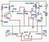
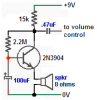
I am using this circuit and simply (I think ) remove S1 so S2 can be used so that its 'one talks and one listens'..one way. I think I have it right, but I was asked to explain in depth the operation. My explainations are useless. Does someone with a more analytical mind have calculations I could show my son to help.
Thanks
 

Attachments

  • intercom1.JPG
    intercom1.JPG
    21.6 KB · Views: 286
experience

A fair bit, he has been getting into 555 timers a bit, mainly calculating stuff so he wants to analyse a real circuit and see calculations too
 
The circuit won't work because the transistor is incorrectly biased and is saturated.

My corrected circuit has a transistor named that has a DC current gain from about 100 to 300.
It has the base bias resistor connected to the collector for DC negative feedback.

1) If the gain of the transistor is 100 then the collector voltage is 6.2V.
2) If the gain of the transistor is 300 then the collector voltage is 3.4V.
 

Attachments

  • intercom preamp.PNG
    intercom preamp.PNG
    21.6 KB · Views: 218
Last edited:
Status
Not open for further replies.

Latest threads

New Articles From Microcontroller Tips

Back
Top