Gary Houston
New Member
Hello Everyone:
I am requesting some help for a timing circuit I need for my model railroad. I need about 10 of these circuits to operate 24VDC, 1.5 amp electromagnets for uncoupling the cars. These electromagnets will be turned on and off through a 24 volt relay. I've looked at commercially available timers, and they are expensive, cheapest I saw was $22. So, I am considering building the timers myself. I have the tools, have built some simple electronic circuits in the past, and I am an electrician by trade.
The source I am dealing with is a 24VDC, 7amp, high quality power supply. What I need to do is have the relay turn on when I push a momentary pushbutton, then turn off after 5 seconds. I believe this is called "one-shot" time delay.
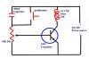
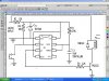
I built the following circuit on an electronics lab board, and it appears to work, but I am certain the voltage on the relay is gradually dropping off instead of turning off all at once. I don't know if this is a bad thing or not, but I am afraid it could lead to diminished contact life. I don't know anything about the transistor except that it is an NPN.
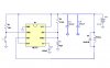
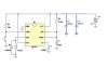
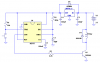
If anyone has suggestions to improve this circuit, or an alternative circuit, I would appreciate the help. Perhaps a 555 Timer circuit could be used?
I am requesting some help for a timing circuit I need for my model railroad. I need about 10 of these circuits to operate 24VDC, 1.5 amp electromagnets for uncoupling the cars. These electromagnets will be turned on and off through a 24 volt relay. I've looked at commercially available timers, and they are expensive, cheapest I saw was $22. So, I am considering building the timers myself. I have the tools, have built some simple electronic circuits in the past, and I am an electrician by trade.
The source I am dealing with is a 24VDC, 7amp, high quality power supply. What I need to do is have the relay turn on when I push a momentary pushbutton, then turn off after 5 seconds. I believe this is called "one-shot" time delay.
I built the following circuit on an electronics lab board, and it appears to work, but I am certain the voltage on the relay is gradually dropping off instead of turning off all at once. I don't know if this is a bad thing or not, but I am afraid it could lead to diminished contact life. I don't know anything about the transistor except that it is an NPN.
If anyone has suggestions to improve this circuit, or an alternative circuit, I would appreciate the help. Perhaps a 555 Timer circuit could be used?
")