Continue to Site

Welcome to our site!

Electro Tech is an online community (with over 170,000 members) who enjoy talking about and building electronic circuits, projects and gadgets. To participate you need to register. Registration is free. Click here to register now.

  • Welcome to our site! Electro Tech is an online community (with over 170,000 members) who enjoy talking about and building electronic circuits, projects and gadgets. To participate you need to register. Registration is free. Click here to register now.

ON561 double FET

Status
Not open for further replies.

panter

New Member
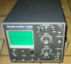
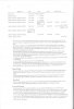
Does anybody have any info/datasheet/replacement on this Tr.? I've looked everywhere but haven't found anything. It's from my Phillips 3226 scope and it died out of a blue. I've found some more unlucky owners of these old but really well built instruments that have the same thing blown.
 
same problem

I have the same problem - trigger not working on Phillips scope because of dead ON561 - but can't source new one or find equilent. Did you you find a solution?
 
Hi,

please register and try at
**broken link removed**

also you may try with RS Components of UK
 
Philips part No's

That's what leaning on schematics does to you...

In fact this is not at all a double transistor, these are two separate fets thermally coupled by a piece of tin. I've even made it reading which fets these were but I've forgot it. try just removing the tin cooler and it will appear, no harm done. These FET's were just commercialy available without any fuss. As I can remember these did have somewhat higher Vds (around 30-40V). Tommorow I'll try to find it and post here.

Shame, they could have said 2xFET whichever those are instead of inventing something no one can find ever and then charge fortune for it. No wonder they went down. (bought by Fluke I believe).

I have a few PM 2517 4 digit DMM's that I'm sorry to throw away. Does anyone have it's schematic/manual so I could adjust it properly?
 
I'll bet they are a matched pair, perhaps in a differential amplifier. The thermal coupling would reduce mismatching due to thermal gradients and thermal transients.
Replacing them with two randomly chosen units may not be satisfactory.
 
ON561 problem.

The problem with the ON561 seems to pop up at a regular rate.
I must admit that I didn't pay much attention to it because I didn't
understand what the problem was and I still don't. If you got a
defective ON561 there's gonna be also a good half which can be
used to select another fet to replace it. So build part of the circuit
from the scope twice on a breadboard and start comparing the
original part with a number of lookalikes which you select from the
Philips program. Possible candidates are BFW10, BFW11 and 2N3823.
But most of these will be obsolete so see what is still available
from other manufacturers.
The description of the ON561 by Panter did ring a bell, I started
digging and I found two similar double fets, the ON235 and the
ON384 which had it's terminals shorted by conductive straps.
I also found similar double fets in a databook of 1976, the BFS21
and the BFS21A. Probably also obsolete.
I'm afraid this post won't be of much help. :D
So build the test circuit and start comparing what is still available.

on1aag.
 
Last edited:
Some years ago I built a diff amp using 2 individual FETs.

I bought 10 of the same FET and plotted the curve of each on graph paper and then used the 2 that were the best match.
 
Well, did it work?
Which ones did you use?
Have a Datasheet on the ones you used?
How about a Schematic?
 
There's someone else tortured by the same thing in this world.

I looked in my files two days ago and i could not find the type i used. Do not worry, apparently it will appear, just if I remember. After all I still do have it's schematics so You can guess the type from there.
My scope is PM 3226 double trace 15MHz If Yours is from the same family it will do. If You send me your mail, i'll scan it for You.

Good luck.
 
Philips and it's mumbo-jumbo.

I've sent schemes to hotwater, I hope he'll post it when He gets it since I'm having trouble here for some unknown reason.

Now the procedure.
Make sure it is actually this FET, I'd first go to:
-check BAV45, it seems critical to me,
-check SG3823 and even BF 240's after, since those can pull up or sink your otherwise good signal away from being visible on screen.
-although tempting do avoid just picking components from the board, it usually doesn't solve anything. Rarely I've been that lucky.

This is not a differential amplifier circuit (although it basically does similar thing), so you can put the good FET on signal path and new (different) one on position set (lower) path. If they have similar thermal coefficients (T correlated Hfe rise) it's going to be OK. If you choose good, just some little trimming of, R506 for instance, will do.

Good luck.
You'll need it. He!
 
Sad story about modern equipment.

Some eight Years ago I've paid dearly for a brand new gadget called Fluke Scopemeter. I gave up an arm, a leg and a portion of an eye for it.

IT WORKED ABOUT SEVERAL DAYS AFTER WARRANTY EXPIRED, which meant two years from purchase. Although serviced in Fluke it just never worked reliably again. Later they said that the problem was in newly developed SMT components and gadgets inside. After I urgently have sold it , i just didn't want to be bothered again, I just got burnt too much.

These two PM3226's, the old junk in my workshop were there, and on the field, for more than 25 years now, with just that one failure. The first goes everywhere with me, and the second sits in the lab. Just for laughs, I must have had about ten car crashes so far, and my father before me, who actually had bought those.
I think I should actually gold-plate these two scopes.

Now, I do see something newer will have to come and I wouldn't like to repeat the previous mistake.
Is there anything on the market that I can trust, or should I just go for Chinese, do as it can, and not bother if it fails?
 
PM3226 Phillips Oscope Schematics.
 

Attachments

  • PM3226_Schematics.pdf
    588.8 KB · Views: 671
OK, those are source followers, serving as input buffers for the input preamp. The best transistor I can find to replace them (looking at datasheets) is **broken link removed**, which is made by Vishay/Siliconix, among others. You will want to rebalance the input stage by grounding the input, centering the balance A or balance B pot, and then tweaking the pot between the sources for DC centering on the screen. You might also have to tweak the trimmer cap that's to GND between the input attenuator and the gate in order to get the frequency response or step response (with no probe, or maybe a 1X probe) back to being flat.
Dean Huster might be of some help in the calibration procedure if I'm wrong and you don't know how to do it. I think Dean serviced Tektronix scopes. This is a Philips, but heck, it's still a scope.

EDIT: If these are too big (maybe input capacitance is too high or something), you need some with Idss > 1ma, because these run at about 1 ma each.

Dean, are you out there?
 
Last edited:
I found some more schematics for PM3200 But, it is in German. I converted to PDF from JPEG Files.
 
Last edited:
Well looks like the site does not want my file tryed to upload for 20 min.
 
Wow!

Now THAT was quick!
I've just posted that a few hours ago.

I'd like to suggest something, I'd like to know something about You guys, might be we could open a new thread and introduce ourselves a bit more.
I'm actually starting to grow feelings for all this, and I just prefer conversating to a group of persons, to writing to a number of nicks.
 
That's what the ****-chat forum is for panter. Post a brief intro of yourself in there and ask for others, and browse the posts in there.
 
Lets try to upload it again the file is 1.8Mb and it will not accept it. the allowed size of a PDF is 9.5Mb. I can't understand why it will not accept it.
 

Attachments

  • 3200.jpg
    3200.jpg
    8.5 KB · Views: 381
  • bl1.jpg
    bl1.jpg
    20.2 KB · Views: 415
  • bl2.jpg
    bl2.jpg
    36.3 KB · Views: 357
  • bl3.jpg
    bl3.jpg
    60.6 KB · Views: 370
  • bl4.jpg
    bl4.jpg
    59.4 KB · Views: 357
  • bl5.jpg
    bl5.jpg
    63.6 KB · Views: 441
  • bl6.jpg
    bl6.jpg
    52.5 KB · Views: 395
  • bl23.jpg
    bl23.jpg
    88.2 KB · Views: 358
  • bl24.jpg
    bl24.jpg
    69.3 KB · Views: 347
  • bl25.jpg
    bl25.jpg
    52.5 KB · Views: 341
Last edited:
Status
Not open for further replies.

Latest threads

New Articles From Microcontroller Tips

Back
Top