Continue to Site

Welcome to our site!

Electro Tech is an online community (with over 170,000 members) who enjoy talking about and building electronic circuits, projects and gadgets. To participate you need to register. Registration is free. Click here to register now.

  • Welcome to our site! Electro Tech is an online community (with over 170,000 members) who enjoy talking about and building electronic circuits, projects and gadgets. To participate you need to register. Registration is free. Click here to register now.

Old RCA Industries Oscilloscope repair.

Status
Not open for further replies.

diy didi

Member
Hi Everyone.
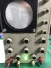
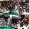
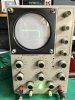
I'm hoping to get some help here. I acquired this old RCA ind. scope. It is identical to the Heathkit O-11. I recapped it and literally checked each resistor. I'm getting a trace on it now. The problem I'm having is that when doing the first step in the calibration procedure, I can't get the dot perfectly round. This leaves me with a the trace as shown when linking the 1Vp-p output of the scope to the vertical input and turning up the vertical gain. It looks like an ellipse and not a straight line. I can actually get a circle showing if I now turn up the HOR gain too. I have substituted most of the tubes, and even bypassed caps across the electrolytics to see if the problem would go away. I have metered out all ground connections, test good. I have spent too much time and money to give up now. Help please :)
 

Attachments

  • IMG_9741.jpg
    IMG_9741.jpg
    1.4 MB · Views: 212
  • A2B614BF-8896-436E-9E05-EB9C3C8F3C94.JPG
    A2B614BF-8896-436E-9E05-EB9C3C8F3C94.JPG
    1 MB · Views: 218
As I don't have a copy of the calibration procedure this is mostly guessing. I am assuming that you are injecting a 1 volt peak to peak sine wave into the vertical input with nothing connected to the horizontal input. (Or the horizontal input shorted out.) It looks to me like some of the vertical signal is getting into the horizontal amplifier with about 90 degrees phase shift. I don't have a schematic of your scope so I can't suggest what could be causing this coupling. Is the signal you are injecting the same frequency as the mains supply in your country ?

Les.
 
Last edited:
Are you using this manual for the calibration routines?

If so, then it might be that one or the other of the two 12AU7 horizontal sweep amps are "weak" and/or unequally matched. Try new ones.

The same might be said about the 12BH7 vert. amps.

Or, there might be a little crossover of the vertical amp circuit into the sweep generator. That, or an external AC signal is slightly affecting the horizontal sweep. Try moving the scope around and observe the dot.
 
I managed to get the scope working. Reasonably. However i can’t get the trace to focus to a nice defined trace. Its slightly thick and fuzzy as can be seen here. In the picture I have the scope connected to my curve tracer.
So i need advise on fixing that.
The curve shown is from a diode. I’ll probably have to reverse the Horizontal or vertical deflection plate wires around?
 

Attachments

  • C2BCBC62-7419-40B8-9F59-E470EBDB1BED.jpeg
    C2BCBC62-7419-40B8-9F59-E470EBDB1BED.jpeg
    664.4 KB · Views: 209
... I’ll probably have to reverse the Horizontal or vertical deflection plate wires around?

With no vertical input signal (so that the "dot" is all that's on the screen) and the horizontal position control at mid-range, does the dot move left and right as you adjust horizontal the position control full left (counterclockwise) and then full right (clockwise)?

If yes, then there no need to swap the horizontal deflection plates' wiring. If no, then swap the wires.
 
Ok I think the scope is working ok now. Thanks for all the help.
I have one more question. The ripple on the output of the ez81 is about 24v peak to peak. It has a 20uf cap as per the schematic, thereafter follows more RC filters on that line.
If i jumper a new 22uf accross that first cap, ripple drops to 12v p-p.
According to the ez81 datasheet max filter C is 50uF.
When jumpering the cap in this way, i see no improvement of the displayed waveform. Should I leave as is or add the extra 22uf?
 
Status
Not open for further replies.

Latest threads

New Articles From Microcontroller Tips

Back
Top