I have a Light Engine that I wish to power. I have a PSU that should provide enough power - however just connecting directly blew the LE up after about 24 hours of operation at the lowest light level.
Understandably - this being the replacement I'm anxious not to repeat this again and want to check (a) if the power seems ok and/or if I should make a power regulator (with some help from the folks here).
I can solder but I have little understanding of power.
The Light Engine is a bit confusing however I read the power requirements as 12V <5A. There's a PSU onboard (which blew last time) that provides a dimmer system for the LED array (using PWM I assume).
Specifications here:
**broken link removed**
The datasheet that comes with this in the box indicates 12V for blue, whereas white etc require 9V. Is it worth attempting to run this a 9V just incase the datasheet is wrong?
My PSU is a 12V 5A supply. This is switched mode.
Specifications here:
RS | Power Supplies | Power Supplies, Inverters, DC/DC Converters & Generators | External Power Supplies | Switch Mode - RS
Should I just be able to connect the LE to the PSU (thinking last time was something defective) or would I be wise to regulate the to a lower voltage and place some resistors in the way along with a fuse to ensure the previous problem doesn't occur again.
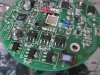
The previous blown LE was a mess - the incoming resistor, a large percentage of the power regulators had burst or burnt. The PCB is slightly warped too!
Help!
Understandably - this being the replacement I'm anxious not to repeat this again and want to check (a) if the power seems ok and/or if I should make a power regulator (with some help from the folks here).
I can solder but I have little understanding of power.
The Light Engine is a bit confusing however I read the power requirements as 12V <5A. There's a PSU onboard (which blew last time) that provides a dimmer system for the LED array (using PWM I assume).
Specifications here:
**broken link removed**
The datasheet that comes with this in the box indicates 12V for blue, whereas white etc require 9V. Is it worth attempting to run this a 9V just incase the datasheet is wrong?
My PSU is a 12V 5A supply. This is switched mode.
Specifications here:
RS | Power Supplies | Power Supplies, Inverters, DC/DC Converters & Generators | External Power Supplies | Switch Mode - RS
Should I just be able to connect the LE to the PSU (thinking last time was something defective) or would I be wise to regulate the to a lower voltage and place some resistors in the way along with a fuse to ensure the previous problem doesn't occur again.
The previous blown LE was a mess - the incoming resistor, a large percentage of the power regulators had burst or burnt. The PCB is slightly warped too!
Help!