Continue to Site

Welcome to our site!

Electro Tech is an online community (with over 170,000 members) who enjoy talking about and building electronic circuits, projects and gadgets. To participate you need to register. Registration is free. Click here to register now.

  • Welcome to our site! Electro Tech is an online community (with over 170,000 members) who enjoy talking about and building electronic circuits, projects and gadgets. To participate you need to register. Registration is free. Click here to register now.

Novel Idea to keep Adj Voltage Regulator (LM1084) Low Output as you Switch ?

Status
Not open for further replies.

blackshadow

New Member
here is my technical challenge:

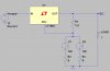
i have a system with different loads and different maximum output voltages (i.e, 5.5V, 8.0V, 9.5V). to do this, i designed an adjustable Voltage regulator with switches to determine the output voltage.

i'm supplying my Vin with 12V since the dropout is around 1.5V.

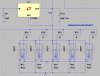
my challenge is this: as i switch from R2 to R3, there is an interval from which R1 is hanging, hence the Vo is close to Vin of 12V. if my load's max Vo is 5.5V, then at the transition, i could be supplying my load with 12V!

is there a way you can prevent this?
please share.
 

Attachments

  • Adj Voltage REgulator Keeping Vo Low upon switch transition.JPG
    Adj Voltage REgulator Keeping Vo Low upon switch transition.JPG
    80.4 KB · Views: 308
Put the switches and switched resistors in parrallel with R1. Keep R2 but make it constant. Make R1/R2 give 9.5v. Switch the other resistors in parrallel with R1 to give 8.0v and 5.5v. Make sure R1 is permanently connected.
 
Put the switches and switched resistors in parrallel with R1. Keep R2 but make it constant. Make R1/R2 give 9.5v. Switch the other resistors in parrallel with R1 to give 8.0v and 5.5v. Make sure R1 is permanently connected.

thanks for the input.

actually i have attached in here the full application of my circuit.
i'm using a 3PDT and POTS to fine tune my output voltage (5.5V to 9.5V).

in my 3PDT, when 1 state is not used, it is grounded so as to output only the Vref of 1.25V(internal reference).
but my problem remains when the 3PDT transitions from 1 state to the other.

please see attached circuit:
 

Attachments

  • Adj Voltage REgulator Keeping Vo Low upon switch transition2.JPG
    Adj Voltage REgulator Keeping Vo Low upon switch transition2.JPG
    135 KB · Views: 336
Put the switches and switched resistors in parrallel with R1. Keep R2 but make it constant. Make R1/R2 give 9.5v. Switch the other resistors in parrallel with R1 to give 8.0v and 5.5v. Make sure R1 is permanently connected.

there is another challenge here, moffy.

a minimum of 10mA needs to flow through R1 to maintain regulation (see datasheet).

the voltage across R1 is equivalent to the internal Zener reference diode (1.25V). the overall output voltage is dictated by R2 values, Vout = 1.25 + I_R1)*R2.
 
I also recommend a scheme such as moffy recommend except I suggest having the bottom resistors switched in parallel. R1 is fixed. R2 would be unswitched. R3 is in parallel with R2 and switched by a SPST relay (S1). R4 is in parallel with R2 also and switched by a second SPST relay (S2). With both relays open adjust R2 to give 9.5V. Close S1 and adjust R3 to give 8.0V. Close S1 and S2 and adjust R4 to give 5.5V.

With those connections the voltage will be 9.5V with both relays open, 8.0V with S1 closed, and 5.5V with both S1 and S2 closed, and it will change between levels with only two SPST relays.
 
Last edited:
I also recommend a scheme such as moffy recommend except I suggest having the bottom resistors switched in parallel. R1 is fixed. R2 would be unswitched. R3 is in parallel with R2 and switched by a SPST relay (S1). R4 is in parallel with R2 also and switched by a second SPST relay (S2). With both relays open adjust R2 to give 9.5V. Close S1 and adjust R3 to give 8.0V. Close S1 and S2 and adjust R4 to give 5.5V.

With those connections the voltage will be 9.5V with both relays open, 8.0V with S1 closed, and 5.5V with both S1 and S2 closed, and it will change between levels with only two SPST relays.

hi crutschow,
this is a novel idea...i had thought it before but my problem is i need to have a maximum of 5.0V supply during any switch transition.

here are the computed resistor values of R2 per desired Vout (Vo=1.25(1+R1/R2);

Vo(load): R2:
9.5 725
8.0 675
7.5 625
7.0 575
6.5 525
6.3 505
6.0 475
5.5 425
5.2 395
5.0 375

the challenge with this is since we need to have an unswitched R2 of 375 ohms such that we always have the low voltage output during transition, its impossible to meet other higher resistor values as the total parallel combination follows the smaller one.

do you think im right and do you have other inputs?
 
thanks for the input.

actually i have attached in here the full application of my circuit.
i'm using a 3PDT and POTS to fine tune my output voltage (5.5V to 9.5V).

in my 3PDT, when 1 state is not used, it is grounded so as to output only the Vref of 1.25V(internal reference).
but my problem remains when the 3PDT transitions from 1 state to the other.

please see attached circuit:
I don't get it. It looks like the ADJ pin is always grounded.
 
hi crutschow,
this is a novel idea...i had thought it before but my problem is i need to have a maximum of 5.0V supply during any switch transition.

here are the computed resistor values of R2 per desired Vout (Vo=1.25(1+R1/R2);

Vo(load): R2:
9.5 725
8.0 675
7.5 625
7.0 575
6.5 525
6.3 505
6.0 475
5.5 425
5.2 395
5.0 375

the challenge with this is since we need to have an unswitched R2 of 375 ohms such that we always have the low voltage output during transition, its impossible to meet other higher resistor values as the total parallel combination follows the smaller one.

do you think im right and do you have other inputs?
My circuit will have no transients above the voltage you are switching to. In other words it smoothly changes voltage levels with no excursions above that.

So why do you need it to go to a low voltage between transitions? That seems an unnecessary complication.
 
My circuit will have no transients above the voltage you are switching to. In other words it smoothly changes voltage levels with no excursions above that.

So why do you need it to go to a low voltage between transitions? That seems an unnecessary complication.

my application needs a low output voltage during switch transition (below the minimum output voltage of 5.0V). note that during the transition, R1 is left hanging, hence the output of LM1084 is close to its input voltage of 12V.
 
my application needs a low output voltage during switch transition (below the minimum output voltage of 5.0V). note that during the transition, R1 is left hanging, hence the output of LM1084 is close to its input voltage of 12V.
Carl asked why you need this. I'm asking the same thing.:p

Also, please reply to post #7.
 
Last edited:
Carl asked why you need this. I'm asking the same thing.:p

Also, please reply to post #7.

the reason i needed to have low voltage output during transistions is: i have around 10 different loads each with defined voltages. it happened that the lowest output voltage i need is 5.0V and it should not exceed. now, if i do have some transition without regard on its voltage output, it could very well exceeed the 5.0V and this will definitely damage the load.

about post#7, there are just some layout errors. the 3PDT is ON-OFF-ON...duringthe OFF state, ADJ is grounded. during each of the ON state, the ADJ is connected to the POT.
 
the reason i needed to have low voltage output during transitions is: i have around 10 different loads each with defined voltages. it happened that the lowest output voltage i need is 5.0V and it should not exceed. now, if i do have some transition without regard on its voltage output, it could very well exceed the 5.0V and this will definitely damage the load.
As I have said twice now, the circuit design I proposed does not have any transients that will exceed the commanded voltage when going to that voltage. What part ot that don't you understand?
 
As I have said twice now, the circuit design I proposed does not have any transients that will exceed the commanded voltage when going to that voltage. What part ot that don't you understand?

hello. sorry for late response but i had this already working. thanks again!
 
Status
Not open for further replies.

Latest threads

New Articles From Microcontroller Tips

Back
Top