Continue to Site

Welcome to our site!

Electro Tech is an online community (with over 170,000 members) who enjoy talking about and building electronic circuits, projects and gadgets. To participate you need to register. Registration is free. Click here to register now.

  • Welcome to our site! Electro Tech is an online community (with over 170,000 members) who enjoy talking about and building electronic circuits, projects and gadgets. To participate you need to register. Registration is free. Click here to register now.

Not sure how to work out the gain of this amplifier

Status
Not open for further replies.

Megamox

New Member
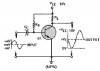
How would you work out the gain of the self biasing amplifier, im not sure how to begin. I was trying to use closed loop gain equations but im not sure how to apply them.

Megamox


EDIT: Sorry just spotted the diagram is wrong, the Resistor Rb should connect to the collector and not the rail!
 

Attachments

  • selfbias.jpg
    selfbias.jpg
    11.2 KB · Views: 807
audioguru said:
The source's impedance is also part of the gain equation.
What Audio is alluding to is that this configuration requires a current source for the input, ie. a source with a relatively high output resistance. What device will supply the signal? eg. a microphone?

If your source has a low output resistance, then you need a different configuration.
 
ljcox said:
If your source has a low output resistance, then you need a different configuration.
This one with a low source impedance would not have any AC negative feedback, so it would have high gain and very high distortion.
Its distortion would be so high that you would be unable to measure its gain.

With a high source impedance then it wouldn't have any gain so would be an inverting piece of wire or attenuator. :wink:
 
Well i must be doing something wrong, maybe my small signal model is incorrect because im just getting massive equations with no way to seperate out the gain expression in the form of:

VIN(Constant1) + Vout(Constant2) = Constant3

When it comes to transistor amplifiers, the only one it seems i can rely on to work with slightly differing hfe's, rises in temperature and leakage currents, is the fixed bias arrangement, with a resistor on the emitter and collector, but for high gains, this usually results in a high collector resistor and therefore higher output impedance, how do you guys get around this? Sometimes i add a cap on the emitter, which gives me a little extra gain but distorts the signal!

Megamox
 
A transistor needs a high value for its collector resistor for high gain.
For very high gain and fairly low distortion, transistors use a constant current source instead of a collector resistor. A constant current source has an extremely high resistance.

If you need to match the high resistance to another transistor's input that has a much lower resistance then use an additional emitter-follower in between.
 
This is in response to the original question.

We need to qualify this discussion with the proviso that the amplifier is biased with Vc ~ Vcc/2. This is done by making Rb ~ beta*RL (not a good biasing method if you want a predictable, stable operating point).

Next, let's make a couple of approximations and assumptions:
1. beta >> 1, therefore Ie ~ Ic
2. Rc >> RL where Rc is the dynamic collector resistance

With these approximations, the voltage gain (with zero source resistance) is approximately -RL/re, where re~0.026/Ie. Ie is dependent on beta. So, first we have to determine the emitter current:

*a bunch of equations boiling down to: (I can post these if anyone wants to see them)

Ie ~ Ic = (Vcc-Vbe)/(RL+RB/beta) where Vbe~0.7

Av=-RL/re, as previously stated


Solving for Av,

Av=-(VCC-Vbe)/(0.026*(1+(RB/(beta*RL)))

This yields low-frequency gain in the 45dB range for VCC=10V, and 100<beta<300.

This gives a voltage gain for zero source impedance. As has been pointed out, high level inputs yield high distortion, and zero impedance sources are not the norm. Nevertheless, if you have a 100uV signal, distortion may be tolerable, and 50 ohm sources are common, as are emitter followers, which can have output impedances in the tens of ohms. If the source impedance Rs is high, gain will be less than Rb/Rs.
 
Thats great, id be interested in seeing those other equations too. Normally i use this type of amp to buffer my electret mic signals, im not sure what their typical impedances are though.
 
Megamox said:
Thats great, id be interested in seeing those other equations too. Normally i use this type of amp to buffer my electret mic signals, im not sure what their typical impedances are though.
I was afraid you were going to say that. <grin>

(1) Vc=Vcc-Ic*RL
(2) Ib*Rb=Vc-Vbe
Solving (2) for Vc,
(3) Vc=Ib*Rb+Vbe
Rearranging (1),
(4) Ic*RL=Vcc-Vc
Substituting (3) for Vc in (4),
(5) Ic*RL=Vcc-Ib*Rb-Vbe
Rearranging (5)
(6) Ic*RL+Ib*Rb=Vcc-Vbe
(7) Ib=Ic/beta by definition
Substitutuing (7) into (6),
(8) Ic*RL*Ic*Rb/beta=Vcc-Vbe
Solving (8) for Ic,
(9) Ic=(Vcc-Vbe)/(RL*Rb/beta)
Q.E.D.
 
I measured the impedance of my electret mic. It is about 3K when it is effectively in parallel with the 10k resistor that feeds current (about 0.5mA) to it from an 8V supply.

I've connected an electret mic directly (through a coupling cap) to the "virtual earth" inverting input of an opamp without a series resistor. The gain is about the same as if the opamp was non-inverting and with the same negative feedback resistor and the feedback resistor to ground the 3K resistance of the mic in parallel with the 10k resistor.

It takes about 1 minute for the current of my electret mic to settle. I guess the FET in it is so small that 0.5mA heats it slowly. :lol:
 
This factor 0.026, is from the diode equation right? The thermal voltage across a diode is 26mv (kt/q) at room temp.
 
It isn't thermal, it is the dynamic change of conductance of a semiconductor junction.
When you increase the current 10 times then the voltage across the junction increases only 26mV.
 
Megamox said:
This factor 0.026, is from the diode equation right? The thermal voltage across a diode is 26mv (kt/q) at room temp.
EDIT:
Hold on!
I posted a bunch of equations, and then got strange result on some of the intermediate answers. I'm re-thinking the whole thing. :oops:

EDIT AGAIN:
OK, I think I fingered out my mistake. This is hopefully correct:

Yes, it's called the diode thermal voltage. I had to refresh my memory on the derivation:

From the diode equation,

I = Is*(e^(qV/kT)-1) where Is is the reverse saturation (leakage) current

I/Is = e^(qV/kT)-1
I/Is ~ e^(qV/kT) for I>>Is

qV/kT = ln(I/Is)

V = (kT/q)*ln(I/Is) = (kT/q)*ln(I) - (kT/q)*ln(Is)

dynamic resistance = dV/dI

dV/dI = (kT/q)/I ; k is Boltzmann's constant, q is the charge on an electron in Coulombs, T is temperature in degrees Kelvin

kT/q = .026 at T=300 Kelvin

dV/dI=.026/I at T=300 Kelvin

The number I remember is (26 ohms)/(current in milliamps)
 
The base-emitter voltage change with temperature shows almost the same angle when the current is changed. So temperature has little effect on a transistor's Re.
 

Attachments

  • vbe.png
    vbe.png
    15.4 KB · Views: 561
audioguru said:
The base-emitter voltage change with temperature shows almost the same angle when the current is changed. So temperature has little effect on a transistor's Re.
True. Re changes about 0.3%/°C, deduced from the fact that room temperature is about 300°K. (1/300~0.3%).
I think kT/q is called a voltage because it does have, in fact, the units of Volts.

k=1.3807e-23 Joules/°Kelvin
q=1.602e-19 Coulombs
T=300°Kelvin at room temperature.

kT/q=0.0259 Joules/Coulomb = .0259 Volts at room temperature.

It is not very sensitive to temperature (at room temperature), as you said, but T is the only variable in the equation. Hence the name "thermal voltage".
 
Status
Not open for further replies.

Latest threads

New Articles From Microcontroller Tips

Back
Top