Scuba Steve
New Member
I have what I would assume is a simple problem, but it is proving quite the opposite for me!
I recently got a Scubapro Sea Glider. This is a diver propulsion vehicle. It is used to pull divers through the water faster than they could swim. The item is not sold/produced in the U.S. any longer and I have been having considerable difficulty finding any kind of technical manuals or schematics.
The circuit is pretty simple. It consists of a 12v 26a dc sealed lead acid battery for power, a switch, and a dc motor with a propeller attached. There is a diode connected to the terminal block of the motor with the cathode on the positive terminal and the anode on the negative terminal.
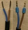
The problem I am having is overheating of the conductors at the terminal block. I used the Sea Glider on a dive today and it just stopped working in the middle of the dive. When I took it apart, I saw that the wire's insulation at the terminal block got so hot that they melted together and melted the terminal block.
Since I got this item used, I am wondering if perhaps the wrong diode has been installed and is causing too much resistance (heat). Is the diode even necessary? What is the diode's function in the circuit?
Thank you in advance for any assistance!
I recently got a Scubapro Sea Glider. This is a diver propulsion vehicle. It is used to pull divers through the water faster than they could swim. The item is not sold/produced in the U.S. any longer and I have been having considerable difficulty finding any kind of technical manuals or schematics.
The circuit is pretty simple. It consists of a 12v 26a dc sealed lead acid battery for power, a switch, and a dc motor with a propeller attached. There is a diode connected to the terminal block of the motor with the cathode on the positive terminal and the anode on the negative terminal.
The problem I am having is overheating of the conductors at the terminal block. I used the Sea Glider on a dive today and it just stopped working in the middle of the dive. When I took it apart, I saw that the wire's insulation at the terminal block got so hot that they melted together and melted the terminal block.
Since I got this item used, I am wondering if perhaps the wrong diode has been installed and is causing too much resistance (heat). Is the diode even necessary? What is the diode's function in the circuit?
Thank you in advance for any assistance!