Continue to Site

Welcome to our site!

Electro Tech is an online community (with over 170,000 members) who enjoy talking about and building electronic circuits, projects and gadgets. To participate you need to register. Registration is free. Click here to register now.

  • Welcome to our site! Electro Tech is an online community (with over 170,000 members) who enjoy talking about and building electronic circuits, projects and gadgets. To participate you need to register. Registration is free. Click here to register now.

Not so simple LED flasher

Status
Not open for further replies.

Powzoom

New Member
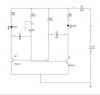
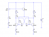
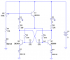
Hey, I'm designing an 2 LED flasher. I have the circuit down, astable multivibrator with npn transistors. It works and I can control the frequency with a 5k pot. But the pot changes the pulse with and the leds flash for different time lengths. How can I control the frequency with a single pot and have both LEDs stay on for the same amount of time?
 

Attachments

  • flasher.jpg
    flasher.jpg
    16.8 KB · Views: 303
I forgot to mention that the only parts I have are resistors, capacitors, and npn transistors. I'm trying to do this without IC's. But I do have most resistor and cap values. I'm thinking I need a schmidt trigger but I'm not entirely sure.
 
You might blow up your LEDs.

Each LED is 1.8V if it is red. Then the transistor saturates with a 0.5V drop and the 30 ohms plus 10 ohms has 6.7V across them and the current is 168mA.

Most ordinary red LEDs have an absolute max allowed current of 30mA or 40mA.

If the LEDs are 3.5V blue or white ones then the 40 ohms has 5V across it and the current is 125mA. Their absolute max allowed current might be 30mA.

Maybe you are lucky and your 9V battery is almost dead.
 
You can do it like this.

EDIT: EM2006 recognized that there needs to be a diode in series with each emitter, instead of the single diode in my original circuit that was connected between both emitters and ground. I have edited the schematic to reflect this.

Nice catch, em2006. Thanks!
 

Attachments

  • multivibrator var  freq sch.PNG
    multivibrator var freq sch.PNG
    19.8 KB · Views: 210
Last edited:
Thanks for the reply. Roff, can you give a brief explanation on how this is working?
Sure. The pot develops a variable voltage on the base of Q3. Q3 is an emitter follower, making a relatively low impedance adjustable voltage source at the tops of R3 and R4. As the voltage is varied, the capacitor (C2 and C3) charging current through R3 and R4 varies, changing the frequency. Since R3 and R4 are connected to the same (variable) voltage source, the duty cycle remains at 50%.
D3 is to prevent the base-emitter junctions of Q1 and Q2 from repeatedly breaking down, which would have the potential of damaging them.
D4 is partial temperature compensation for the base-emitter junction of Q3, so the frequency will be more stable as temperature changes.
R7 prevents the voltage on R3 and R4 from going so low that the circuit ceases to oscillate. You can change R1, R2, R3, R4, and the capacitors to suit your frequency and LED current requirements.
As drawn, the frequency will change over ≈3:1 range from one end of the pot to the other.
 
...D3 is to prevent the base-emitter junctions of Q1 and Q2 from repeatedly breaking down, which would have the potential of damaging them....

To prevent the base-emitter junctions of Q1 and Q2 from repeatedly breaking down, I think two diodes are required, one for each transistor, according to schematic attached:
 

Attachments

  • multivibrator var freq sch2.PNG
    multivibrator var freq sch2.PNG
    5.4 KB · Views: 184
To prevent the base-emitter junctions of Q1 and Q2 from repeatedly breaking down, I think two diodes are required, one for each transistor, according to schematic attached:
You're right. I'll edit my original schematic, and give you credit.

Thanks!
 
just use LEDs for D3, they'll both protect the transistors and light-up.
 
I know but the emitter breakdown voltage of the transistors is 5V giving a total breakdown of 10V.
 
just use LEDs for D3, they'll both protect the transistors and light-up.
You have to be careful with that technique, because the emitter diode peak current is twice the collector peak current. The collector current jumps immediately to the quasi-steady-state value when the transistor turns on. The emitter current jumps to twice that value, then decays exponentially to approximately the same final value.
 
Last edited:
Status
Not open for further replies.

New Articles From Microcontroller Tips

Back
Top