Continue to Site

Welcome to our site!

Electro Tech is an online community (with over 170,000 members) who enjoy talking about and building electronic circuits, projects and gadgets. To participate you need to register. Registration is free. Click here to register now.

  • Welcome to our site! Electro Tech is an online community (with over 170,000 members) who enjoy talking about and building electronic circuits, projects and gadgets. To participate you need to register. Registration is free. Click here to register now.

Not getting the ideal output

Status
Not open for further replies.

Varun Dua

New Member
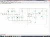
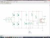
I implemented this circuit and am getting the output desired but what I observe is that if I dont connect anything across the Zener diode (i.e. if I remove everything after the capacitor connected parallel to zener diode) i'm getting a constant a 12V but if I connect everything I dont get a 12V across the Zener voltage regulator, basically there's a voltage drop.

Could you pls help in identifying where I'm going wrong or maybe I have chosen some wrong value of resistor or capacitor somewhere which is causing this drop, because I need a 12V across the zener voltage regulator when everything is connected.
Untitled.jpg Waveform.jpg
 
1 It would help if your schematic was more readable. It is difficult to see the component values.
2 What is the supply? Is it supposed to be the 240v mains? If so this circuit is dangerous and should not be built as drawn.
3 Reducing the rectified mains with a resisitive dropper to give 12v is a very bad idea and the cause of your "voltage drop" when the rest of the circuit is connected.
4 Your supply smoothing capacitor C3 is probably too low a value, is in the wrong place.

All in all a good example of a bad circuit.

JimB
 
Ok uploading a more readable digram of it.
Yes the supply is supposed to be 230V AC Supply, and I'm taking proper measures to keep it away from any human contact.
So according to you changing the value of resistors and capacitor wont help in this case in obtaining a 12V output when the rest of circuit is connected? Maybe try to identify which is the load that is causing this voltage drop?
 

Attachments

  • Ckt.jpg
    Ckt.jpg
    478.2 KB · Views: 159
Ok made few more changes and now getting the right output..
https://obrazki.elektroda.pl/2404526100_1435052033.jpg

One last doubt, this circuit would work only if I have a 230V AC Supply but incase if I have a 230V DC Supply, all the DC would get blocked by the capacitor and so we would not get any output. So any chnages that I can make to this circuit so that It works also for a 230V DC?
 
Last edited:
I agree with JimB that this circuit is hazardous. Why not use an old cell-phone charger or similar to provide a safer low voltage supply?
R5,R6,R7,T1,T2 draw current which causes a voltage drop across R1 and R3. If their only purpose is to provide a power-on trigger pulse for the 555 then there are easier ways to do that (e.g just a cap from TRIG to GND and a resistor from TRIG to Vcc).

Edit: Why no smoothing capacitor directly after the rectifier bridge? Why are C1 and C2 connected across the AC supply?
 
Last edited:
He got thrown off AAC with this dumb circuit. Do not encourage him...
 
I am closing this thread due to the dangerous nature of the design shown. It doesn't matter if it is within human contact, it can still cause severe damage to components, which could explode and harm people or property.

I will bring it up with the rest of the moderation staff, but I expect this thread will remain closed. Varun Dua , we strongly encourage you to use a step-down transformer. What you show is very hazardous and should not be built.
 
Status
Not open for further replies.

Latest threads

New Articles From Microcontroller Tips

Back
Top